optocoupler
Sometimes known as an optoelectronic coupler, opto-isolator, photocoupler, or optical isolator.
A solid-state relay is sometimes referred to as an optocoupler, but in this encyclopedia it has a separate entry. An optocoupler is a relatively simple device consisting of a light source (usually an LED) and a light sensor, both embedded in one package. It is used primarily for isolation rather than to switch a high current. A solid-state relay can be thought of as a substitute for an electromagnetic relay, usually has additional components in its package, and is intended to switch currents of at least 1A.
An optocoupler allows one section of a circuit to be electrically isolated from another. It protects sensitive components, such as logic chips or a microcontroller, from voltage spikes or incompatible voltages in other sections of a circuit. Optocouplers are also used in medical devices where a patient has to be protected from any risk of electric shock, and are used in devices which conform with the MIDI standard for digital control of music components.
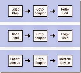
In Figure 5-1, three possible applications for an optocoupler are suggested:
Top
The output from a logic chip passes through an optocoupler to an inductive load such as a relay coil, which may create voltage spikes that would be hazardous to the chip.
Center
The noisy signal from an electromagnetic switch passes through an optocoupler to the input of a logic chip.
Bottom
The low-voltage output from a sensing de- vice on a human patient passes through an optocoupler to some medical equipment, such as an EEG machine, where higher voltages are used.
Internally, an optocoupler works on the same principle as a solid-state relay. An LED is embedded on the input side, shining light through an interior channel or transparent window to a sensing component that is embedded on the output side. Because the only internal connection is a light beam, the input and output of the optocoupler are isolated from each other.
Figure 5-1. Possible applications for a photocoupler. See text for details.
Isolation transformers were traditionally used for this purpose prior to the 1970s, when optocouplers became competitive. In addition to being smaller and cheaper, an optocoupler can also pass slow-changing signals or on-off DC states which a transformer would ignore.
More recently, inductive and capacitive coupling components have become available in surface- mount packages that are competitive with optocouplers for high-speed data transfer. They al- so claim to be more durable. Because of the gradual reduction in output from an LED, the performance of an optocoupler degrades over time, and is typically rated for up to 10 years.
How It Works
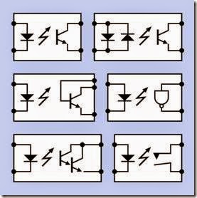
output. Schematic symbols for this type are shown in Figure 5-2:
Top left
The most common generic form.
Top right
Two diodes on the input side allow the use of alternating current.
Center left
An additional terminal allows addition of bias to the photosensitive base of the output transistor, to reduce its sensitivity.
Center right
An Enable signal can be used as the input to the NAND, suppressing or enabling the out- put.
Bottom left
A photodarlington allows higher emitter current.
Bottom right
Relatively uncommon, and is also used for a solid-state relay.
In each symbol, the diode is an LED, and the zigzag arrow indicates light that is emitted from it. A pair of straight arrows, or wavy arrows, may al- ternatively be used.
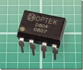
An optocoupler in through-hole DIP format is shown in Figure 5-3.
An optical switch can be thought of as a form of optocoupler, as it contains an LED opposite a sensor. However, the LED and the sensor are separated by an open slot, to allow a thin moving
The LED in an optocoupler almost always emits light in the near-infrared part of the spectrum, and is matched to the sensitivity of a photo- transistor, or a photodiode, or (less often) a photoresistor that provides the output. Photo- sensitive triacs and SCRs are also sometimes used.
The most common type of optocoupler uses a bipolar phototransistor with an open-collector object to pass through, interrupting the light beam as a means of detecting the event. It is categorized as a sensor in this encyclopedia, and will be found in Volume 3.
Figure 5-2. Six variants of schematic symbols that may be used to represent an optocoupler. See text for details.
Figure 5-3. An optocoupler in through-hole 8-pin DIP format.
Variants
Internal Sensors
Historically, a photoresistor (often referred to as a photocell) was the first type of sensor to be used. It has a more linear response than other sensor types, but its response is much slower. It is still found in audio applications. “Stomp box” pedals used by guitarists typically contain an optocoupler that employs a photoresistor, and are valued for their linearity and their immunity from the mechanical wear, contamination, and “scratchi- ness” that builds up over time in a potentiometer. Optocouplers also eliminate ground loops, which tend to be induced by small differences in ground potential, introducing hum or buzz in audio applications when two or more power supplies are tied together.
The type of optocoupler that contains a photo- resistor and is commonly used by musicians was initially trademarked as a Vactrol, and that term is still used generically. Vactrols have also been used to provide audio compression in telephone voice networks, and were used in photocopiers and photographic exposure meters, but these applications are now obsolete.
Photoresistors are becoming uncommon be- cause of their cadmium content, which is unlaw- ful in many countries (especially in Europe) be- cause of its environmental toxicity.
A photodiode provides the fastest response time in an optocoupler, limited primarily by the char- acteristics of the LED that shines light upon it. A PIN diode can respond in less than a nanosecond; its acronym is derived from its fabrication from p-type and n-type semiconductor layers with an intrinsic layer connecting them. This additional layer can be responsive to light. When the diode is slightly reverse-biased, a photon entering the intrinsic layer can dislodge an electron, enabling current to flow. The reverse bias enlarges the ac- tive area and enhances the effect. In this mode, the PIN acts like a photoresistor, appearing to re- duce its resistance in response to light.
When the PIN is used in photovoltaic mode, no bias is applied, and the component actually gen- erates a small voltage (less than 1VDC), like a solar cell, in response to incoming light. Where an op- tocoupler uses a MOSFET on its output side, as many as 30 photodiodes may be connected in series to develop the necessary threshold voltage to trigger the transistor. This arrangement is common in solid-state relays.
A bipolar phototransistor is a slower-speed de- vice but is still usually capable of a 5µs response time or better. Its open collector requires external voltage and a pull-up resistor to deliver a pos- itive output so long as the phototransistor is nonconductive. When the LED turns on, the pho- totransistor sinks current, effectively creating a low output. In this way, the optocoupler functions like an inverter, although some variants include a noninverting output.
Basic Optocoupler Types
An optocoupler with high linearity will respond more proportionally to variations in current to its LED. High Speed optocouplers are used for high- frequency data transfer. Logic-output optocouplers have a clean high/low output transition, rather than an analog output, which varies with fluctuations in the input. Linearity is of importance only where an optocoupler is being used to transmit an analog signal with some fidelity. Some logic-output optocouplers provide the function of a Schmitt trigger on their output side.
While optocouplers are available in various pack- age formats, the DIP style with six or eight pins remains popular, providing sufficient physical space for the LED, the sensor, and a light channel, while providing good electrical isolation.
Variants may have two or four optocouplers com- bined in one package. A bidirectional optocou- pler may consist of two optocouplers in parallel, inverted with respect to each other.
Values
In a datasheet, the characteristics of primary im- portance in an optocoupler are:
• CTR is the Current Transfer Ratio, the ratio of maximum output current to input current, expressed as a percentage. With a bipolar phototransistor output, 20% is a typical minimum CTR. With a photodarlington output, the CTR may be 1,000% but the bandwidth is much lower—the response time may be measured in microseconds rather than nanoseconds. Optocouplers with a photo- diode output have a very low CTR, and their output is in microamps. However, they pro- vide the most linear response.
• VCE(MAX) is the maximum collector-emitter voltage difference (in an optocoupler with a bipolar phototransistor output). Values from 20 to 80 volts are common.
• VISO is the maximum potential difference, in VDC, between the two sides of the optocoupler.
• IMAX is the maximum current the transistor can handle, generally in mA.
• Bandwidth is the maximum transmittable signal frequency, often in the range of 20kHz to 500kHz.
The LED in an optocoupler typically requires 5mA at a forward voltage of 1.5V to 1.6V.
The maximum collector current on the output side of an optocoupler is unlikely to be higher than 200mA. For higher output currents, a solid- state relay should be considered. It provides photo-isolation on the same basis as an optocoupler, but high-current versions tend to be considerably more expensive.
How to Use It
The primary purpose of an optocoupler is to pro- vide protection against excessive voltage—from transients, incompatible power supplies, or equipment with unknown characteristics. If a de- vice is designed to be plugged into a USB port on a computer, for instance, the computer may be isolated via an optocoupler.
A series resistor for the LED is not built into most optocouplers, because the value of the resistor will depend on the input voltage that is used. Care must be taken to determine what the max- imum voltage on the input side will be, and a series resistor should be chosen to reduce cur- rent appropriately. Allowance should be made for some degradation in the performance of the LED over time.
For an optocoupler with an open-collector out- put, a pull-up resistor is necessary in most applications. The voltage from the optocoupler must be matched to the input requirements of other components, and the collector current must re- main within the specified limits. Some trial and error in resistor selection may be necessary.
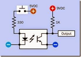
In Figure 5-4, a schematic shows typical component values in a test circuit using a pushbutton as input. The separation of the two power sup- plies is emphasized by the different color shades used for the positive and negative symbols. Al- though the input side and the output side of an optocoupler may be used with a common ground, this defeats its purpose in providing complete isolation between the sections of the circuit.
The pinouts for an optocoupler must be checked carefully in the manufacturer’s datasheet. While the input for an 8-pin DIP chip is usually applied to pins 2 and 3, the output pin functions are not standardized and will vary depending on the in- ternal configuration of the chip. An optocoupler such as the Optek D804, with an enable function using an internal NAND gate, requires its own power supply.
Where an optocoupler allows an external con- nection to the base of its internal bipolar output phototransistor, reverse bias applied to this pin will decrease the sensitivity of the optocoupler but can increase its immunity to noise on the in- put side.
What Can Go Wrong
Age
Because optocouplers are typically rated for only 10 years of average use, the age of a component may cause it to fail.
Figure 5-4. Typical values for a series resistor (to protect the LED) and pull-up resistor (to control current and volt- age on the output side) in an optocoupler test circuit.
LED Burnout
Because the LED is hidden inside the component, there is no immediate indication of its performance. A meter can be inserted into the circuit on the input side to determine if current is passing through the LED. A meter set to measure volts can be used to discover whether the LED is imposing a normal voltage drop. While significant overload will cause immediate burnout, slightly exceeding the current rating of the LED may have more pernicious consequences, as the LED may not fail until days or weeks have passed without any sign of trouble. The failure of the optocoupler will be unexpected and difficult to determine.
Transistor Burnout
Here again the damage caused by excessive cur- rent may be progressive, occurring over a prolonged period. The easiest way to test an opto- Overload conditions on the input or the output side of an optocoupler will be the most likely cause of failure.
coupler that may have failed is by removing it from the circuit. A socketed DIP package is preferable for this purpose.


