digital potentiometer
A digital potentiometer is also known as a digitally adjustable potentiometer, a digitally controlled potentiometer, a digitally programmed potentiometer (with acronym DPP), a digpot, or a digipot. The terms are functionally interchangeable. Because the abbreviation pot is often used to describe an analog potentiometer, some people refer to digital potentiometers colloquially as digital pots. In printed documentation, the letters in pot may be capitalized. Because it is an abbreviation, not an acronym, it is not capitalized here.
Because this component enables digital control of a variable voltage, it is a mixed signal device. It is classified here as an analog chip because it primarily emulates the function of an analog device. It may be thought of as a form of digital-analog converter, although this encyclopedia does not have a section devoted to that type of component or to analog-digital converters, as their application is relatively specialized.
What It Does
This component is an integrated circuit chip that emulates the function of an analog potentiometer. It is often described as being programmable, meaning that its internal resistance can be changed via a control input.
Digital potentiometers are particularly suited for use in conjunction with a microcontroller, which can control the internal resistance of the component. Possible applications include adjustment of the pulse width of an oscillator or multistable multivibrator (e.g., using the Control pin of a 555 timer chip); adjustment of the gain in an op-amp; specification of voltage delivered by a voltage regulator; and adjustment of a band- pass filter.
A digital potentiometer in combination with a microcontroller may also be used in conjunction with a pair of external buttons or a rotational encoder, to adjust the gain of an audio amplifier and for similar applications.
Advantages
A digital potentiometer offers significant advan- tages over an analog potentiometer:
• Reliability. The digital component may be rated for as many as a million cycles (each storing the wiper position in an internal memory location). An analog component may be capable of just a few thousand ad- justment cycles.
• Digital interface.
• Elimination of long signal paths or cable runs. The digital potentiometer can be placed close to other chips, whereas an an- alog potentiometer often has to be some distance away to enable control by the end user. Reduction in the length of signal paths can reduce capacitive effects, while elimination of cable runs will reduce manufacturing costs.
• Reduction in size and weight compared with a manual potentiometer.
A digital potentiometer also has some disadvantages:
• Its internal resistance is somewhat affected by temperature.
• It is not usually capable of passing significant current. Few chips can sink or source more than 20mA at the output, and 1mA is common. The output is primarily intended for connection with other solid-state components that have high impedance.
• Users may prefer the immediacy and tactile feel of a knob attached to an analog poten- tiometer, rather than a pair of buttons or a rotational encoder.
How It Works
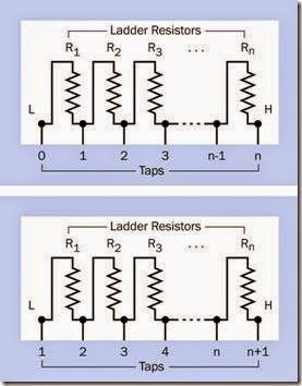
A digital potentiometer changes the point at which a connection is made along a ladder of many fixed resistors connected in series inside the chip. Each end of the ladder, and each inter- section between two adjacent resistors, is known as a tap. The pin that can connect with any of the taps is referred to as the wiper, because it emu- lates the function of a wiper in an analog potentiometer. In reality, a digital potentiometer does not contain a wiper or any other moving parts.
A fully featured digital potentiometer allows access to each end of the ladder through two pins that are often labeled “high” and “low,” even though they are functionally interchangeable (except in the case of a component that simulates a logarithmic taper, as described later). The “low” end of the ladder is sometimes numbered
1. In this case, if there are n resistors, the “high” end of the ladder will be numbered n. Alternatively, if the “low” end of the ladder is numbered 1, and there are n resistors, the “high” end will be numbered n+1. This principle is illustrated in Figure 8-1.
Figure 8-1. Available wiper connections to a resistor lad- der inside a digital potentiometer, showing two numbering systems that may be used.
The “low” pin on a digital potentiometer may be identified as L, or A, or RL, or PA in a datasheet, while the “high” pin may be identified as H, or B, or RH, or PB and the pin that accesses the wiper is typically identified as W, or RW, or PW. Letters L, H, and W are used below. Although the L and H pins are functionally interchangeable, their labels are useful to identify which direction the W connection will move in response to an external signal.
Digital potentiometers are available with as few as 4 or as many as 1,024 taps, but common values are 32, 64, 128, or 256 taps, with 256 being the most common.
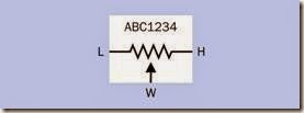
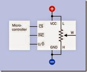
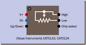
No specific schematic symbol represents a digital potentiometer. Often the component is shown as an analog potentiometer symbol inside a box that has a part number, as suggested in Figure 8-2. Control pins and the power supply may be omitted if the schematic is just intended to show logical connections. Alternatively, if the digital potentiometer is depicted in a schematic where it is connected with other components such as a microcontroller, multiple pins and functions may be included, as shown in Figure 8-3. The pins additional to L, H, and W are explained below.
Figure 8-2. There is no single specific symbol to represent a digital potentiometer. It may be shown using an analog potentiometer symbol in a box with a part number, as suggested here, where power connections and additional pins are omitted for clarity.
Figure 8-3. If a digital potentiometer appears in a schematic where it is connected with other components such as a microcontroller, additional pins and functions may be indicated. This generic representation of a digital potentiometer shows some of the functions that can be included.
Variants
A dual digital potentiometer contains two com- plete units, while a quad contains four. Triples exist but are relatively uncommon. A few chips contain six potentiometers. Multiple digital potentiometers in a chip can be used as the digital equivalent of ganged analog potentiometers, for simultaneous synchronized adjustment of multiple inputs in an audio system (two channels in a stereo amplifier, or more in a surround-sound system).
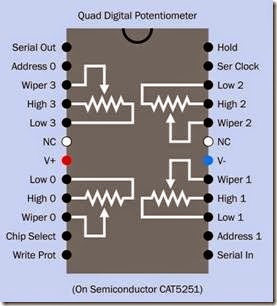
The pinouts of a sophisticated quad digital potentiometer chip are shown in Figure 8-4. Other quad chips have different pinouts and capabili- ties; there is no standardized format as there is with digital logic chips. In this example, the high/ low states of Address 0 and Address 1 select one of the four internal resistor ladders, numbered 0 through 3. The Chip Select pin makes the whole chip either active or inactive. The Write Protect pin disables writing to the internal wiper memory. The Serial Clock pin inputs a reference pulse stream to which the serial input data must be synchronized. The Hold pin pauses the chip while data is being transmitted, allowing the data transmission to be resumed subsequently. The NC pins have no connection.
Volatile and Nonvolatile Memory Any type of digital potentiometer requires memory to store its current wiper position, and this memory may be volatile or nonvolatile. Nonvolatile memory may be indicated in a datasheet by the term NV.
A digital potentiometer with volatile memory will typically reset its wiper to a center-tap position if power is disconnected and then restored. A digital potentiometer with nonvolatile memory will usually restore the most recently used wiper position, provided the chip is fully powered down and then fully powered up without glitches in the supply. If a microcontroller is being used to control the digital potentiometer, it can store the most recent resistance value in its own nonvolatile memory, in which case the type of memory in the potentiometer becomes irrelevant.
Figure 8-4. Pinouts of a sophisticated quad digital potentiometer chip. Other chips will have different pinouts and capabilities. This example is available in surface-mount formats only. See text for details.
Taper
Digital potentiometers are available with linear taper or logarithmic taper. In the former, each resistor in the ladder has the same value. In the latter, values are chosen so that the cumulative resistance between the wiper and the L end of the ladder increases geometrically as the wiper steps toward the H end of the ladder. This is useful in audio applications where sound intensity that increases exponentially may seem to increase linearly when perceived by the human ear.
A microcontroller can emulate logarithmic steps by skipping some taps in the ladder in a digital potentiometer, but this will result in fewer increments and lower precision.
Data Transfer
Digital potentiometers are mostly designed to use one of three serial protocols:
• SPI. This acronym is derived from serial peripheral interface, a term trademarked by Motorola but now used generically. The standard is adapted in various radically different ways among digital potentiometers.
• I2C. More correctly printed as I2C and properly pronounced “I squared C,” this acronym is derived from the term inter-integrated circuit. Developed by Philips in the 1990s, it is a relatively slow-speed bus-communication protocol (up to 400kbps or 1Mbps in its basic form). It is built into some microcontrollers. The standard is more uniformly and rigorously defined than SPI.
• Up/down, also sometimes known as push- button or increment/decrement protocol.
Both SPI and I2C are supported by many micro- controllers, including the Atmel AVR at the heart of the Arduino.
These three systems for controlling a digital potentiometer are described in more detail in the following sections.
SPI
This is the most widely used protocol, but when reading datasheets, a lot of care must be taken to determine how it varies in each case.
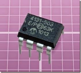
The Microchip 4131-503, shown in Figure 8-5, uses SPI protocol. It contains 128 resistors and can be powered by 1.8VDC to 5.5VDC.
The one feature that all versions of SPI have in common is that a series of high/low pulses is interpreted by the chip as a set of bits whose value defines a tap point in the resistor ladder. In computer terminology, every tap point has an ad- dress. The incoming bits define the address, after which the status of an additional input pin can tell the chip to move the wiper to that location.
Typically, there will be a chip select pin, identified as CS; a serial data input pin, identified as SDA, SI, DIN, or a similar acronym; and a serial clock pin, identified as SCL, SCLK, or SCK, which must receive a stream of pulses to which the high/low data input pulses must be synchronized. In addition, the SPI protocol allows bidirectional (duplex) serial communication. Only a minority of digital potentiometers make use of this capability, but where it exists, a serial data output pin may be labeled SDO. Alternatively, one pin may be multiplexed to enable both input and output, in which case it may be labeled SDI/SDO.
Figure 8-5. This digital potentiometer uses SPI protocol. See text for details.
If a pin is active-low, a bar (a horizontal line) will be printed above its acronym.
The most common type of digital potentiometer has 255 resistors and therefore 256 tap points, which have addresses numbered 0 through 255, each of which can be specified by a sequence of eight data bits constituting one byte. However, a different coding system will be applied in chips that have a different number of taps. In a 32-tap component, for instance, data is still sent in groups of eight bits, but only the first five bits define a tap address, while the remaining three are interpreted as commands to the chip.
Most 256-tap chips use an SPI protocol in which two eight-bit bytes are sent, the first being interpreted by the chip as a command, while the second specifies a tap address. Each manufacturer may use a different set of command codes, and these will vary among chips even from the same manufacturer.
Most commonly, three wires are used for data transmission and control (causing these chips to be described as 3-wire programmable potentiometers).
CS is usually, but not always, pulled low to activate the digital potentiometer for input. A series of low or high states is then applied to the data- input pin. Each time the clock input changes state (usually on the rising edge of the clock pulse) the state of the data input is copied to a shift register inside the chip. After all the bits have been clocked in, CS can change from low to high, causing the contents of the shift register to be copied into a decoder section of the chip. The first bit received becomes the most significant bit in the decoder. The value of the eight bits is de- coded, and the chip connects the W pin directly to the corresponding tap along the ladder of 255 internal resistors.
I2C Protocol
The I2C specification is controlled by NXP Semi- conductors (formerly Philips), but can be used in commercial products without paying licensing fees. Only two transmission lines are required: one carrying a clock signal, the other allowing bidirectional data transfer synchronized with the clock (although many digital potentiometers use the I2C connection only to receive data). The pins are likely to be identified by the same acronyms as the pins on a chip that uses SPI protocol.
As in SPI, a command byte is followed by a data byte, although the command set differs from that of SPI and will also differ among various I2C chips. Full implementation of I2C allows multiple devices to share a single bus, but this capability may remain unused.
Up/Down Protocol
This simpler, asynchronous protocol does not re- quire a clock input. The chip will respond to data pulses that are received at any speed (up to its maximum speed), and the pulse widths can be inconsistent.
Each pulse moves the wiper connection one step up or down the ladder. While this has the advantage of simplicity, the taps are not addressable, and consequently the wiper cannot skip to any tap without passing through intervening taps incrementally. This is not an inconvenience when the potentiometer controls audio gain, which is a primary application.
In some chips, an increment pin, usually labeled INC, receives pulses while the high or low state of a second pin, usually labeled U/D, determines whether each pulse will step the wiper up the ladder or down the ladder.
In other chips, pulses to an Up pin will step the wiper up the ladder, while pulses to a Down pin will step the wiper down the ladder.
Either of these chip designs can be referred to as a two-wire type. If an additional chip-select pin is included (labeled CS on datasheets), this type of digital potentiometer can be referred to as a three-wire type. The chip select pin is likely to be active-low, meaning that so long as it has a high state, the chip will ignore incoming signals.
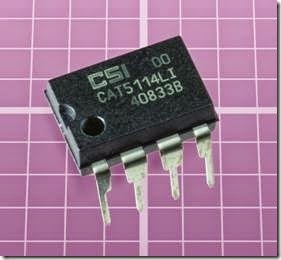
The CAT5114 shown in Figure 8-6 uses an U/D pin. It contains 31 resistors, is available in 8-pin DIP or surface-mount formats, and can be powered by 2.5VDC to 6VDC. Each of its logic inputs draws only 10µA.
In six-pin chips the INC pin is omitted, one of the H, L, or W pins will be omitted, and the U/D pin will function differently. When CS is pulled low, the chip checks the state of the U/D pin. If it is high, the chip goes into increment mode; if it is low, the chip goes into decrement mode. So long as CS remains low, each transition of the U/D pin from low to high will either increment or decrement the wiper position, depending on the mode that was sensed initially. When CS goes high, further transitions on the U/D pin will be ignored until CS goes low again, at which point the procedure repeats.
Figure 8-6. This digital potentiometer contains 31 resistors and uses the simplest up/down protocol to step from one tap to the next.
The chip does not provide any feedback regarding the position of its wiper, and consequently a control device such as a microcontroller cannot know the current wiper position. If the chip has nonvolatile memory (as is the case in many up/ down digital potentiometers), it will resume its previous wiper location at power-up, but here again a control device will have difficulty deter- mining what that position is. Therefore, in its basic form, an up/down chip is only appropriate for simple tasks, especially in response to up/down pushbuttons.
Other Control Systems
A few digital potentiometers use a parallel inter- face. Because they are relatively uncommon, they are not included here.
Connections and Modes
Some variants of digital potentiometers minimize the chip size and number of connections by limiting accessibility to the internal resistor lad- der. In a chip designed to function in rheostat mode, the W pin is eliminated and the chip moves an internal connection point to change the resistance between the H and L pins.
In some variants, the low end of the ladder is permanently, internally connected with ground, and the L pin is omitted. In other variants, one end of the ladder is unconnected inside the chip.
A chip designed to function in voltage divider mode will include all three pins—H, L, and W— except in some instances where the low end of the ladder is grounded internally.
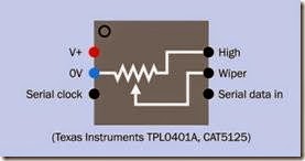
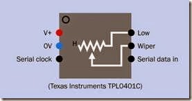
Variants are shown in Figures 8-7, 8-8, 8-9, and 8-10. Because some pins may be omitted, and there is no standardization of function among the pins that do exist, circuits and chips must be examined carefully prior to use.
Figure 8-7. Some digital potentiometers minimize chip size and provide specialized functionality by eliminating pins. In the variant shown here, the W pin provides a volt- age between H and an internal ground connection. The chip is controlled via I2C serial protocol.
Figure 8-8. In this variant, the H end of the internal resistor ladder is allowed to float inside the chip, and the digital potentiometer functions as a rheostat. The chip is con- trolled via I2C serial protocol.
Figure 8-9. This variant provides a variable resistance be- tween the H pin and an internal connection with negative ground. Pin 5 is omitted. The chip is controlled by up/ down pulses.
Figure 8-10. This variant provides a variable resistance between H and L pins, without allowing either end of the resistor ladder to float. The W pin is omitted, as the wiper is tied internally to the H pin. The chips listed are con- trolled by up/down pulses.
Values
A primary limitation of digital potentiometers is that they cannot withstand significant current. This may prevent them from being substituted for an analog potentiometer unless changes are made in the circuit. H, L, and W pins are usually unable to source or sink continuous, sustained current exceeding 20mA.
Wiper resistance is the resistance that is added internally by the wiper. This is nontrivial; it is often around 100Ω, and can be as high as 200Ω.
Typical end-to-end resistance of the ladder of internal resistors may range from 1K to 100K. Val- ues of 1K, 10K, and 100K are common.
While the number of taps is likely to be a power of two in chips where the taps are addressable, up/down chips are not so constrained and may contain, for example, 100 taps.
The end-to-end resistance of a whole ladder may vary by as much as 20% from one sample of a chip to the next. Among resistor ladders in digital potentiometers sharing the same chip (i.e., in du- al or quad chips) the variation will be much smaller.
Almost all digital potentiometers are designed for a supply voltage of 5V or less. The H and L pins are not sensitive to polarity, but the voltage ap- plied to either of them must not exceed the sup- ply voltage.
How to Use It
switching. Potentiometers with this feature may include phrases such as “glitch free” in their datasheets.
Digital potentiometers that are intended primarily for audio applications often have 32 taps spaced at intervals of 2dB. This will be sufficient to satisfy most listeners.
Achieving Higher Resolution
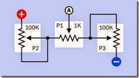
For sensitive applications where a resolution with more than 1,024 steps is required, multiple digital potentiometers with different step values can be combined. One way of doing this is shown in Figure 8-11. In this circuit, the wipers of P2 and P3 must be moved in identical steps, so that the total resistance between the positive power sup- ply and negative ground remains constant.
These two potentiometers could be contained in While most microcontrollers contain one or more analog-digital converters that change an analog input to an internal numeric value, a microcontroller cannot create an analog output. A digital potentiometer adds this functionality, although applications will be restricted by its limitation on current.
An up/down digital potentiometer can be con- trolled directly by a pair of pushbuttons, one of which will increase the resistance value while the other will reduce it. The pushbuttons must be debounced when used in this way. An alternative to pushbuttons is a rotational encoder, which emits a stream of pulses when its shaft is turned. In this case, an intermediate component (probably a microcontroller) will usually interpret the pulse stream and change it to a format that the digital potentiometer can understand.
Where a digital potentiometer is used in audio applications, it should be of the type that moves the wiper connection from one tap to another during a zero crossing of the audio signal (i.e., that is, at the moment when the AC input signal pass- es through 0V on its way from positive to negative or negative to positive). This suppresses the “click” that otherwise tends to occur during
a dual chip, and would receive identical up/down commands. P1 is at the center of the voltage divider formed by P2 and P3, and is adjusted separately to “fine tune” the output voltage that is sensed at point A.
If all three of the potentiometers in this circuit contain 100 taps, a combined total of 10,000 resistance steps will be possible.
Figure 8-11. If all three digital potentiometers in this schematic have 100 taps, and the wipers of P2 and P3 are moved in synchronization, the voltage measured at point A can have a high resolution of up to 10,000 steps.
What Can Go Wrong
Noise and Bad Inputs
Because a digital potentiometer is capable of receiving data at speeds as high as 1MHz, it is sensitive to brief input or power fluctuations, and can misinterpret them as instructions to move the wiper—or can misinterpret them as command codes, in a component using SPI or I2C serial protocol.
To minimize noise in the power supply, some manufacturers recommend installing a 0.1µF capacitor as close as possible to the power supply pin of the component. In addition, it is obviously important to provide clean input signals. This means thorough debouncing of any electromechanical switch or pushbutton inputs.
Wrong Chip
The wide diversity of input protocols and pinouts creates many opportunities for installation error.
Up/down, SPI, and I2C protocol require totally different pulse streams. Many manufacturers offer components that are distinguished from each other by just one or two digits in their part numbers, yet have radically different functionality.
If more than one specific type of digital potentiometer may be used during circuit development, they should be stored carefully to avoid inadvertant substitutions. Using the wrong chip may be particularly confusing in that an inappropriate input protocol will still produce some results, al- though not those which were intended.
Controller and Chip Out of Sync
As noted in the discussion of data transmission protocols, most digital potentiometers are not capable of providing feedback to confirm the position of the internal wiper. A designer may wish to include a power-up routine which establishes the state of the digital potentiometer by resetting it to a known position, at one end of its scale or the other.
Nonlinear Effects
While the end-to-end resistance of the resistor ladder inside a digital potentiometer is not likely to be affected significantly by changes in temperature, the resistance at the wiper is more heat sensitive.
In an up/down chip, there can be differential errors between incremental and decremental modes. In other words, if a tap is reached by step- ping up to it incrementally, the resistance be- tween the W pin and H or L may not be quite the same as if the same tap is reached by stepping down to it decrementally. The difference may not be significant, but may be puzzling for those who are unfamiliar with this phenomenon.
Some differences may be found among resistors in a ladder. That is, in a supposedly linear digital potentiometer, each resistor may differ in value slightly from the next.
Data Transfer Too Fast
When using a microcontroller to send data to a digital potentiometer, a small delay may be necessary between pulses, depending on the microcontroller’s clock speed. A digital potentiometer may require a minimum pulse duration of 500ns. Check the manufacturer’s datasheet for details.

