MICROELECTRONIC SYSTEM DESIGN CONCEPTS
You should understand the terminology used in microelectronics to become an effective and knowledgeable technician. You should be familiar with packaging concepts from a maintenance standpoint and be able to recognize the different types of assemblies. You should also know the electrical and environmental factors that can affect microelectronic circuits. In the next section of this topic we will define and discuss each of these areas.
TERMINOLOGY
As in any special electronics field, microelectronics terms and definitions are used to clarify communications. This is done so that everyone involved in microelectronics work has the same knowledge of the field. You can imagine how much trouble you would have remembering 10 or more different names and definitions for a resistor. If standardization didn’t exist for the new terminology, you would have far more trouble understanding microelectronics. To standardize terminology in microelectronics, the Navy has adopted several definitions with which you should become familiar. These definitions will be presented in this section.
Microelectronics
Microelectronics is that area of electronics technology associated with electronics systems built from extremely small electronic parts or elements. Most of today’s computers, weapons systems, navigation systems, communications systems, and radar systems make extensive use of microelectronics technology.
Microcircuit
A microcircuit is not what the old-time technician would recognize as an electronic circuit. The old- timer would no longer see the familiar discrete parts (individual resistors, capacitors, inductors, transistors, and so forth). Microelectronic circuits, as discussed earlier, are complete circuits mounted on a substrate (integrated circuit). The process of fabricating microelectronic circuits is essentially one of building discrete component characteristics either into or onto a single substrate. This is far different from soldering resistors, capacitors, transistors, inductors, and other discrete components into place with wires and lugs. The component characteristics built into microcircuits are referred to as ELEMENTS rather than discrete components. Microcircuits have a high number of these elements per substrate compared to a circuit with discrete components of the same relative size. As a matter of fact, microelectronic circuits often contain thousands of times the number of discrete components. The term HIGH EQUIVALENT CIRCUIT DENSITY is a description of this element-to-discrete part relationship. For example, suppose you have a circuit with 1,000 discrete components mounted on a chassis which is 8 ´ 10 ´ 2 inches. The equivalent circuit in microelectronics might be built into or onto a single substrate which is only 3/8 x 1 x 1/4 inch. The 1,000 elements of the microcircuit would be very close to each other (high density) by comparison to the distance between discrete components mounted on the large chassis. The elements within the substrate are interconnected on the single substrate itself to perform an electronic function. A microcircuit does not have any discrete components mounted on it as do printed circuit boards, circuit card assemblies, and modules composed exclusively of discrete component parts.
Microcircuit Module
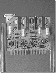
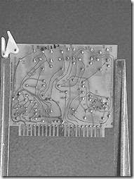
Microcircuits may be used in combination with discrete components. An assembly of microcircuits or a combination of microcircuits and discrete conventional electronic components that performs one or more distinct functions is a microcircuit module. The module is constructed as an independently packaged, replaceable unit. Examples of microcircuit modules are printed circuit boards and circuit card assemblies. Figure 1-35 is a photograph of a typical microcircuit module.
Figure 1-35.—Microcircuit module.
Miniature Electronics
Miniature electronics includes miniature electronic components and packages. Some examples are printed circuit boards, printed wiring boards, circuit card assemblies, and modules composed exclusively of discrete electronic parts and components (excluding microelectronic packages) mounted on boards, assemblies, or modules. MOTHER BOARDS, large printed circuit boards with plug-in modules, are considered miniature electronics. Cordwood modules also fall into this category. Miniature motors, synchros, switches, relays, timers, and so forth, are also classified as miniature electronics.
Recall that microelectronic components contain integrated circuits. Miniature electronics contain discrete elements or parts. You will notice that printed circuit boards and circuit card assemblies are mentioned in more than one definition. To identify the class (microminiature or miniature) of the unit, you must first determine the types of components used.
Q37. Standardized terms improve what action between individuals?
Q38. Microcircuit refers to any component containing what types of elements?
Q39. Components made up exclusively of discrete elements are classified as what type of electronics?
SYSTEM PACKAGING
When a new electronics system is developed, several areas of planning require special attention. An area of great concern is that of ensuring that the system performs properly. The designer must take into account all environmental and electrical factors that may affect the system. This includes temperature, humidity, vibration, and electrical interference. The design factor that has the greatest impact on you, as the technician, is the MAINTAINABILITY of the system. The designer must take into account how well you will be able to locate problems, identify the faulty components, and make the necessary repairs. If a system cannot be maintained easily, then it is not an efficient system. PACKAGING, the method of enclosing and mounting components, is of primary importance in system maintainability.
Levels of Packaging
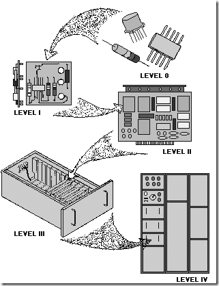
For the benefit of the technician, system packaging is usually broken down to five levels (0 to IV). These levels are shown in figure 1-36.
Figure 1-36.—Packaging levels.
LEVEL 0.—Level 0 packaging identifies nonrepairable parts, such as integrated circuits, transistors, resistors, and so forth. This is the lowest level at which you can perform maintenance. You are limited to simply replacing the faulty element or part. Depending on the type of part, repair might be as simple as plugging in a new relay. If the faulty part is an IC, special training and equipment will be required to accomplish the repair. This will be discussed in topic 2.
LEVEL I.—This level is normally associated with small modules or submodules that are attached to circuit cards or mother boards. The analog-to-digital (A/D) converter module is a device that converts a signal that is a function of a continuous variable (like a sine wave) into a representative number sequence in digital form. The A/D converter in figure 1-37 is a typical Level I component. At this level of
maintenance you can replace the faulty module with a good one. The faulty module can then be repaired at a later time or discarded. This concept significantly reduces the time equipment is inoperable.
Figure 1-37.—Printed circuit board (pcb).
LEVEL II.—Level II packaging is composed of large printed circuit boards and/or cards (mother boards). Typical units of this level are shown in figures 1-37 and 1-38. In figure 1-38 the card measures 15 ´ 5.25 inches. The large dual inline packages (DIPs) are 2.25 inches x 0.75 inch. Other DIPs on the pcb are much smaller. Interconnections are shown between DIPs. You should also be able to locate a few discrete components. Repair consists of removing the faulty DIP or discrete component from the pcb and replacing it with a new part. Then the pcb is placed back into service. The removed part may be a level 0 or I part and would be handled as described in those sections. In some cases, the entire pcb should be replaced.
Figure 1-38.—Printed circuit board (pcb).
LEVEL III.—Drawers or pull-out chassis are level III units, as shown in figure 1-36. These are designed for accessibility and ease of maintenance. Normally, circuit cards associated with a particular subsystem will be grouped together in a drawer. This not only makes for an orderly arrangement of subsystems but also eliminates many long wiring harnesses. Defective cards are removed from such drawers and defective components are repaired as described in level II.
LEVEL IV.—Level IV is the highest level of packaging. It includes the cabinets, racks, and wiring harnesses necessary to interconnect all of the other levels. Other pieces of equipment of the same system classified as level IV, such as radar antennas, are broken down into levels 0 to III in the same manner.
During component troubleshooting procedures, you progress from level IV to III to II and on to level 0 where you identify the faulty component. As you become more familiar with a system, you should be able to go right to the drawer or module causing the problem.
Q40. Resistors, capacitors, transistors, and the like, are what level of packaging? Q41. Modules or submodules attached to a mother board are what packaging level? Q42. What is the packaging level of a pcb?


