A.c. Circuits Containing Both Inductive and Capacitive Reactances
A.c. circuits that contain both an inductor and a capacitor have interesting characteristics because of the opposing effects of L and C. X L and XC may be treated as reactors which are 180 degrees out of phase. As shown in figure 1-2, the vector for XL should be plotted above the baseline; vector for XC, figure 1-3, should be plotted below the baseline. In a series circuit, the effective reactance, or what is termed the RESULTANT REACTANCE, is the difference between the individual reactances. As an equation, the resultant reactance is:
Q-1. What is the relationship between frequency and the values of (a) XL, (b) XC, and (c) R?
Q-2. In an a.c. circuit that contains both an inductor and a capacitor, what term is used for the difference between the individual reactances?
RESONANCE
For every combination of L and C, there is only ONE frequency (in both series and parallel circuits) that causes XL to exactly equal XC; this frequency is known as the RESONANT FREQUENCY. When the resonant frequency is fed to a series or parallel circuit, X L becomes equal to XC, and the circuit is said to be RESONANT to that frequency. The circuit is now called a RESONANT CIRCUIT; resonant circuits are tuned circuits. The circuit condition wherein XL becomes equal to XC is known as RESONANCE.
Each LCR circuit responds to resonant frequency differently than it does to any other frequency. Because of this, an LCR circuit has the ability to separate frequencies. For example, suppose the TV or radio station you want to see or hear is broadcasting at the resonant frequency. The LC "tuner" in your set can divide the frequencies, picking out the resonant frequency and rejecting the other frequencies. Thus, the tuner selects the station you want and rejects all other stations. If you decide to select another station, you can change the frequency by tuning the resonant circuit to the desired frequency.
RESONANT FREQUENCY
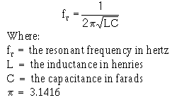
As stated before, the frequency at which XL equals XC (in a given circuit) is known as the resonant frequency of that circuit. Based on this, the following formula has been derived to find the exact resonant frequency when the values of circuit components are known:
There are two important points to remember about this formula. First, the resonant frequency found when using the formula will cause the reactances (XL and XC) of the L and C components to be equal. Second, any change in the value of either L or C will cause a change in the resonant frequency.
An increase in the value of either L or C, or both L and C, will lower the resonant frequency of a given circuit. A decrease in the value of L or C, or both L and C, will raise the resonant frequency of a given circuit.
The symbol for resonant frequency used in this text is f. Different texts and references may use other symbols for resonant frequency, such as fo, Fr, and fR. The symbols for many circuit parameters have been standardized while others have been left to the discretion of the writer. When you study, apply the rules given by the writer of the text or reference; by doing so, you should have no trouble with nonstandard symbols and designations.
The resonant frequency formula in this text is:
By substituting the constant .159 for the quantity
the formula can be simplified to the following:
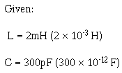
Let’s use this formula to figure the resonant frequency (fr). The circuit is shown in the practice tank circuit of figure 1-4.
The important point here is not the formula nor the mathematics. In fact, you may never have to compute a resonant frequency. The important point is for you to see that any given combination of L and C can be resonant at only one frequency; in this case, 205 kHz.
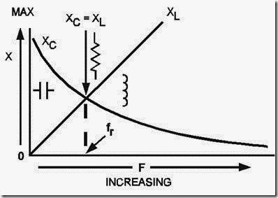
The universal reactance curves of figures 1-2 and 1-3 are joined in figure 1-5 to show the relative values of XL and XL at resonance, below resonance, and above resonance.
Figure 1-5.—Relationship between XL and XC as frequency increases.
First, note that fr, (the resonant frequency) is that frequency (or point) where the two curves cross. At this point, and ONLY this point, XL equals XC. Therefore, the frequency indicated by fr is the one and only frequency of resonance. Note the resistance symbol which indicates that at resonance all reactance is cancelled and the circuit impedance is effectively purely resistive. Remember, a.c. circuits that are resistive have no phase shift between voltage and current. Therefore, at resonance, phase shift is cancelled. The phase angle is effectively zero.
Second, look at the area of the curves to the left of fr. This area shows the relative reactances of the circuit at frequencies BELOW resonance. To these LOWER frequencies, XC will always be greater than XL. There will always be some capacitive reactance left in the circuit after all inductive reactance has been cancelled. Because the impedance has a reactive component, there will be a phase shift. We can also state that below fr the circuit will appear capacitive.
Lastly, look at the area of the curves to the right of f. This area shows the relative reactances of the circuit at frequencies ABOVE resonance. To these HIGHER frequencies, XL will always be greater than XC. There will always be some inductive reactance left in the circuit after all capacitive reactance has been cancelled. The inductor symbol shows that to these higher frequencies, the circuit will always appear to have some inductance. Because of this, there will be a phase shift.
RESONANT CIRCUITS
Resonant circuits may be designed as series resonant or parallel resonant. Each has the ability to discriminate between its resonant frequency and all other frequencies. How this is accomplished by both series- and parallel-LC circuits is the subject of the next section.
NOTE: Practical circuits are often more complex and difficult to understand than simplified versions. Simplified versions contain all of the basic features of a practical circuit, but leave out the nonessential features. For this reason, we will first look at the IDEAL SERIES-RESONANT CIRCUIT— a circuit that really doesn’t exist except for our purposes here.


