SUMMARY
This chapter introduced you to the principles of tuned circuits. The following is a summary of the major subjects of this chapter.
THE EFFECT OF FREQUENCY on an INDUCTOR is such that an increase in frequency will cause an increase in inductive reactance. Remember that XL = 2pfL; therefore, XL varies directly with frequency.
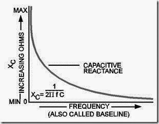
THE EFFECT OF FREQUENCY on a CAPACITOR is such that an increase in frequency will cause a decrease in capacitive reactance. Remember that
therefore, the relationship between XC and frequency is that XC varies inversely with frequency.
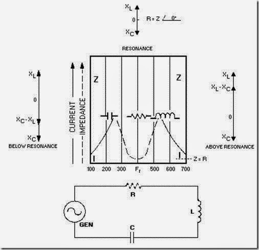
RESULTANT REACTANCE X = (XL – X C) or X = (XC – XL). XL is usually plotted above the reference line and X C below the reference line. Inductance and capacitance have opposite effects on the current in respect to the voltage in a.c. circuits. Below resonance, XC is larger than XL, and the series circuit appears capacitive. Above resonance, XL is larger than XC, and the series circuit appears inductive. At resonance, XL = XC, and the total impedance of the circuit is resistive.
A RESONANT CIRCUIT is often called a TANK CIRCUIT. It has the ability to take energy fed from a power source, store the energy alternately in the inductor and capacitor, and produce an output which is a continuous a.c. wave. The number of times this set of events occurs per second is called the resonant frequency of the circuit. The actual frequency at which a tank circuit will oscillate is determined by the formula:
IN A SERIES-LC CIRCUIT impedance is minimum and current is maximum. Voltage is the variable, and voltage across the inductor and capacitor will be equal but of opposite phases at resonance. Above resonance it acts inductively, and below resonance it acts capacitively.
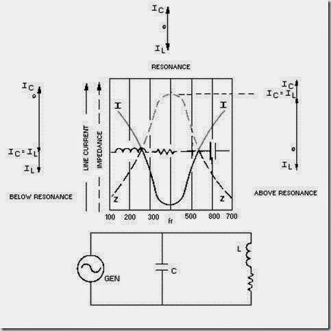
IN A PARALLEL-LC CIRCUIT impedance is maximum and current is minimum. Current is the variable and at resonance the two currents are 180 degrees out of phase with each other. Above resonance the current acts capacitively, and below resonance the current acts inductively.
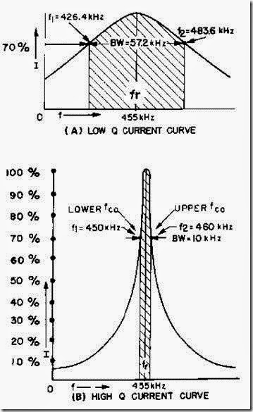
THE "Q" OR FIGURE OF MERIT of a circuit is the ratio of XL to R. Since the capacitor has negligible losses, the circuit Q becomes equivalent to the Q of the coil.
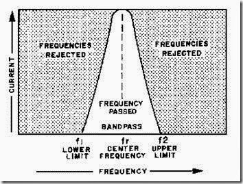
THE BANDWIDTH of a circuit is the range of frequencies between the half-power points. The limiting frequencies are those at either side of resonance at which the curve falls to .707 of the maximum value. If circuit Q is low, you will have a wide bandpass. If circuit Q is high, you will have a narrow bandpass.
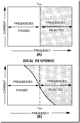
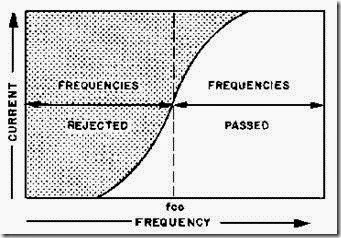
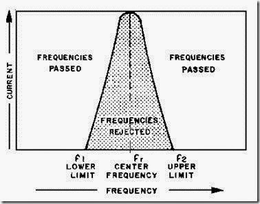
A FILTER CIRCUIT consists of a combination of capacitors, inductors, and resistors connected so that the filter will either permit or prevent passage of a certain band of frequencies.
A LOW-PASS FILTER passes low frequencies and attenuates high frequencies.
A HIGH-PASS FILTER passes high frequencies and attenuates low frequencies.
A BANDPASS FILTER will permit a certain band of frequencies to be passed.
A BAND-REJECT FILTER will reject a certain band of frequencies and pass all others.
A SAFETY PRECAUTION concerning series resonance: Very high reactive voltage can appear across L and C. Care must be taken against possible shock hazard.
ANSWERS TO QUESTIONS Q1. THROUGH Q21.
A-1.
a. XL varies directly with frequency.
X L = 2pfL
b. XC varies inversely with frequency.
c. Frequency has no affect on resistance.
A-2. Resultant reactance. A-3.
A-4. Decreases.
A-5. Impedance low Current high.
A-6. Nonresonant (circuit is either above or below resonance).
A-7. Inductor magnetic field.
A-8. Capacitor.
A-9. Natural frequency or resonant frequency (f r).
A-10. Maximum impedance, minimum current.
A-11. At the resonant frequency. A-12.
A-13. Bandwidth of the circuit.
A-14. A filter.
A-15.
a. Low-pass.
b. High-pass
c. Bandpass.
d. Band-reject.
A-16. High-pass filter, low-frequency discriminator, or low-frequency attenuator.
A-17. Low-pass filter, high-frequency discriminator or high-frequency attenuator.
A-18. At low-frequency, a capacitor acts as an open and an inductor acts as a short. At high-frequency, a capacitor acts as a short and an inductor acts as an open.
A-19. Frequency cutoff (fco).
A-20. Bandpass.
A-21. Band-reject.


