SUMMARY
This chapter has presented information on oscillators. The information that follows summarizes the important points of this chapter.
WAVE GENERATORS can be classified according to the SINUSOIDAL or NONSINUSOIDAL waveforms produced.
SINUSOIDAL WAVE GENERATORS (oscillators) produce a sine wave of constant amplitude and frequency. There are three ways to control the frequency of sine-wave generators: (1) RC NETWORKS, (2) LC NETWORKS, and (3) CRYSTALS.
NONSINUSOIDAL WAVE GENERATORS (oscillators) generate complex waveforms such as SQUARE WAVES, RECTANGULAR WAVES, SAWTOOTH WAVES, TRAPEZOIDAL WAVES,
and TRIGGERS. Nonsinusoidal wave generators are often called RELAXATION OSCILLATORS.
A BASIC OSCILLATOR can be thought of as an amplifier that provides itself with a signal input.
An OSCILLATOR is a device that converts dc power to ac power at a predetermined frequency.
The requirements for an oscillator are AMPLIFICATION, REGENERATIVE FEEDBACK, and a FREQUENCY-DETERMINING NETWORK.
An oscillator has two stability requirements, AMPLITUDE STABILITY and FREQUENCY STABILITY.
FEEDBACK is the process of transferring energy from a high-level point in a system to a low-level point. Feedback that aids the input signal is REGENERATIVE or POSITIVE. Feedback that opposes the input signal is DEGENERATIVE or NEGATIVE.
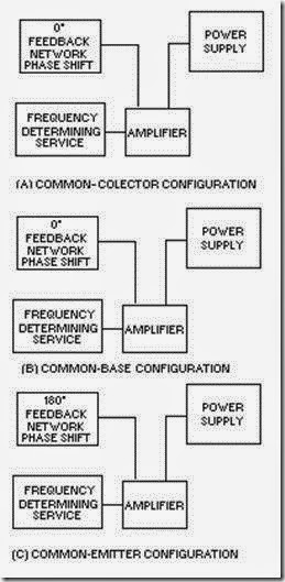
The three basic circuit configurations used for oscillators are COMMON COLLECTOR, COMMON BASE, and COMMON EMITTER.
In the COMMON-COLLECTOR configuration there is no PHASE SHIFT between input and output. It is not necessary for the feedback network to provide a phase shift. Voltage gain is less than unity (one) and power gain is low so it is very seldom used as an oscillator.
In the COMMON-BASE configuration, there is no PHASE SHIFT between input and output. It is not necessary for the feedback network to provide a phase shift. Voltage and power gain are high enough to give satisfactory operation in an oscillator circuit.
In the COMMON-EMITTER configuration, there is a 180-degree PHASE SHIFT between input and output. The feedback network must provide another phase shift of 180 degrees. It has a high power gain.
The ARMSTRONG OSCILLATOR is used to produce a sine-wave output of constant amplitude and fairly constant frequency.
An oscillator in which dc power is supplied to the transistor through the tank circuit, or a portion of the tank circuit, is SERIES FED.
An oscillator in which dc power is supplied to the transistor through a path separate and parallel to the tank circuit is PARALLEL or SHUNT FED.
The HARTLEY OSCILLATOR is used to produce a sine-wave output of constant amplitude and fairly constant frequency.
The COLPITTS OSCILLATOR is used to produce a sine-wave output of constant amplitude and fairly constant frequency within the rf range. The identifying features of the Colpitts oscillator are the split capacitors.
The RESISTIVE-CAPACITIVE (RC) FEEDBACK OSCILLATOR is used to produce a sine- wave output of relatively constant amplitude and frequency. It uses RC networks to produce feedback and eliminate the need for inductors in the resonant circuit.
CRYSTAL OSCILLATORS are those oscillators that use a specially cut crystal to control the frequency. The crystal can act as either a capacitor or inductor, a series-tuned circuit, or a parallel-tuned circuit.
PULSED OSCILLATORS are sinusoidal oscillators that are turned on and off for a specific time duration. The frequency of a pulsed oscillator is determined by both the input gating pulse and the resonant frequency of the tank circuit.
A HARMONIC is a sinusoidal wave having a frequency that is a multiple of the fundamental frequency.
FREQUENCY MULTIPLIERS (HARMONIC GENERATORS) are special class C amplifiers that are biased at 3 to 10 times the normal cutoff. They are used to generate a frequency that is a multiple or harmonic of a lower frequency.
A BUFFER AMPLIFIER decreases the loading effect on the oscillator by reducing the interaction between the load and the oscillator.
ANSWERS TO QUESTIONS Q1. THROUGH Q23.
A-1. Sinusoidal and nonsinusoidal. A-2. RC, LC, and crystal.
A-3. Relaxation oscillators. A-4. Oscillator.
A-5. Amplification, regenerative feedback, and frequency-determining device. A-6. Regenerative or positive.
A-7. Inductive and capacitive. A-8. Armstrong.
A-9. Hartley. A-10. Colpitts.
A-11. Common collector (CC), common emitter (CE), and common base (CB).
A-12. Feedback coil. Armstrong uses a separate coil. Hartley uses a tapped coil.
A-13. In the series-fed Hartley oscillator, dc flows through the tank circuit.
A-14. Split capacitors.
A-15. Resistor-capacitor networks.
A-16. Because of the losses encountered in the RC networks. A-17. Four-section.
A-18. Maximum. A-19. Minimum.
A-20. Pulsed oscillators. A-21. Negative.
A-22. Second harmonic.
A-23. Reduce interaction between oscillator and load.


