LEAKAGE FLUX
Some of the lines of flux produced by the primary winding do not link the turns of the secondary winding in most transformers. The magnetic circuit for this primary leakage flux is in air. In other words, the leakage flux does not follow the circuit path through the core. This flux links the turns of the primary winding, but it does not link the turns of the secondary winding. Because the leakage flux uses part of the impressed primary voltage, there is a reactance voltage drop in the primary winding. The result is that both the secondary flux linkages and the secondary induced voltage are reduced.
A second leakage flux links the secondary turns but not the primary turns. This flux also has its magnetic path in air and not in the core. The secondary leakage flux is proportional to the secondary current. There is a resulting reactance voltage drop in the secondary winding. Both the primary and the secondary leakage fluxes reduce the secondary terminal voltage of the transformer as the load increases. The leakage flux of
a transformer can be controlled by the type of core used. The placement of the primary and secondary coils on the legs of the core is also a controlling factor in the amount of leakage flux produced.
EXCITING CURRENT AND CORE LOSSES
When there is no load attached to the secondary winding, the current input to the primary winding usually ranges from 2% to 5% of the full-load current. The primary current at no load is called the exciting current. This current supplies the alternating flux and the losses in the transformer core. These losses are known as core losses and consist of eddy current losses and hysteresis losses. As the magnitude of the alternating flux increases and decreases, the metal core is cut by the flux, as are the turns of the primary and secondary coils. Voltages are thus induced in the metal core and give rise to eddy currents. These eddy currents circulate through the core and cause I2 R loses, which must by supplied by the exciting current. Eddy current losses can be reduced by laminating the core structure. Each lamination normally is coated with a film of insulating varnish. When a protective film of varnish is not used, the oxide coating on each lamination still reduces the eddy cur- rent losses to some extent.
The core structure also experiences a hysteresis loss. In each second, the millions of molecules in the core structure are reversed many times by the alternating flux. Power is required to overcome this molecular friction in the core. This power is supplied by the primary winding. To decrease the amount of power used, a special steel such as silicon steel is used. Eddy current and hysteresis losses are called the core losses. In a typical transformer, these losses are relatively small.
To supply the magnetizing flux, the exciting current has a relatively large component of quadrature or magnetizing current. A smaller in-phase component of current supplies the core losses. For an actual transformer, the no-load power factor ranges between 0.05 and 0.10 lagging. This means that the phase angle between the exciting current and the impressed primary voltage is between 84° and 87° lagging. The exciting current can be measured by a method known as the core loss open-circuit test.
Measuring Core Losses
The connections for the core loss test are shown in Figure 13–3A. The high-voltage winding of the transformer is rated at 2400 V. The low-voltage winding is rated at 240 V and is used as the primary side of the transformer. This arrangement makes it convenient to use 240 V for the potential circuits of the wattmeter and voltmeter. The test circuit can also use 240 V safely.
CAUTION: The high-voltage winding leads and terminal connections must be well insulated and barricaded so that no one can contact this high-voltage circuit. This test circuit can be considered hazardous because the transformer operates as a stepup transformer with a 2400-V potential across the leads of the high-voltage secondary winding.
The losses of a transformer at no load are small. This means that instrument errors must be checked. The dashed-line voltmeter connections in Figure 13–3A mean that the
voltmeter is to be disconnected when a wattmeter reading is to be taken. The voltmeter must be disconnected so that the wattmeter will not indicate the power taken by the voltmeter.
If the rated voltage and frequency are used in this circuit, then the rated alternating flux exists in the core. The resulting core loss is normal. The wattmeter indicates the core loss in watts, and the ammeter indicates the exciting current.
The error introduced by the copper loss in the primary can be neglected. The following example shows why this is so. The primary resistance (R ) equals 0.007 W. The primary copper loss is 102 times 0.007 equals 0.7 W. This value of 0.7 W is small enough to be neglected, when compared to the 140 W indicated by the wattmeter. This assumption still holds for smaller transformers because they have smaller values of exciting current and core losses.
The core loss can also be measured when the high-voltage side of the transformer is used as the primary winding. In this case, a 2400-V source is required. After compensating for instrument losses, it is found that the core loss is the same as for the case when the
low-voltage side of the transformer is used as the primary. This result is to be expected because both windings are wound on the same core. Because the same number of ampere- turns will produce the same alternating flux, when either winding is used as the primary, the core loss in watts will be the same for both cases.
Figure 13–3B shows the vector relationship between the exciting current (10 A), its in-phase component (1 A), and its quadrature (magnetizing) lagging component. The phase angle between the line voltage and the exciting current is 84.3°. The core loss is 240 W.
PROBLEM 3
Statement of the Problem
Figure 13–3A shows the connections for a core loss test on a 50-kVA, 60-Hz, single-phase transformer. The high-voltage winding of the transformer is rated at 2400 V and the low-voltage winding is rated at 240 V. The low-voltage winding is used as the primary for the core loss test. With 240 V applied to the primary winding, the wattmeter indicates a core loss of 240 W. The ammeter indicates an exciting current of 10 A. Determine
1. the power factor and the phase angle.
2. the in-phase component of the current.
3. the quadrature lagging or magnetizing component of the current.
Solution
COPPER LOSSES USING DIRECT CURRENT
The copper losses of a transformer consist of the I2 R losses in both the primary and secondary windings. If the effective resistance of each winding is known, the copper losses of a transformer can be found readily. Recall that the approximate ac resistance of an alternator is found by multiplying the dc resistance by 1.4 or 1.5. For transformers, however, the windings are not embedded in the slots of a stator, but consist of coils wound on a core. This means that the difference between the ohmic resistance and the effective resistance is small. Generally, the ac or effective resistance of a transformer is obtained by measuring the dc resistance of the winding and multiplying it by 1.1.
Figure 13–4 shows the connections required to measure the dc, or ohmic resistance, of a winding. A current-limiting resistance is used in this circuit. It is important that small dc currents be used. The voltmeter should be disconnected before the circuit is deenergized because the windings are highly self-inductive. The large value of the induced voltage could damage the voltmeter movement and pointer.
PROBLEM 4
Statement of the Problem
The resistance for each winding of a 50-kVA, 2400/240-V, 60-Hz, single-phase, step- down transformer is measured with direct current. The dc resistance of the high-voltage winding is 0.68 W. The low-voltage winding has a dc resistance of 0.0065 W. Determine
1. the effective resistance of each winding.
2. the total copper losses at full load.
Solution
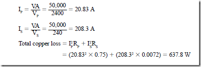
2. The transformer losses are small. Thus, when determining the full-load current rating of each winding, it can be assumed that the volt-ampere input and output are the same:
TRANSFORMER LOSSES AND EFFICIENCY
Transformer losses consist of copper losses and core losses. Copper losses are the I2 R losses in the primary and secondary windings. These losses increase as the load current in the primary and secondary windings increases. The copper losses can be calculated from the current and the effective resistance for each winding.
Transformer efficiency is the ratio of the output in watts to the input in watts. The load connected to the transformer secondary often has a power factor other than unity. In such cases, the output is the product of the secondary voltage and current plus the power factor of the load. The input equals the output plus the total losses. These losses include the cop- per losses and the core losses.
The core losses can be measured as shown in Figure 13–3A. These losses consist of eddy current and hysteresis losses. The core losses remain nearly constant at all load points if the frequency and primary voltage remain constant.
If the losses are known or can be calculated, for any given load point, the transformer efficiency can be determined. The basic efficiency formula is as follows:
The efficiency of a transformer can be found by loading it at various percentages of the load from no load to full load and measuring the input and output power values. However, the losses are quite small. Unless extremely accurate instruments are used, the
results will be of little value. For example, the efficiency of a transformer at full load is usually in the range from 96% to 98%. Typically, an indicating wattmeter can have an error of one percent. This means that the error in the calculations can be as much as 50%. In addition, this method requires various loading devices having the correct cur- rent, voltage, and power factor ratings. It is both inconvenient and costly to provide such loading devices. This is particularly true for transformers having extremely large kVA capacities.
The preferred method of determining the efficiency of a transformer is to measure the losses and add this value to the nameplate output to obtain the input. The following example shows how the efficiency is obtained by measuring the losses.
PROBLEM 5
Statement of the Problem
The 50-kVA, 2400/240-V transformer described in problems 3 and 4 delivers the rated load output at a unity power factor. The core loss was found to be 240 W. The primary cop- per loss was 325.4 W and the secondary copper loss was 312.4 W. Find the efficiency at the rated output and unity power factor.
Solution
The Short-Circuit Test
Another method of measuring the copper losses of a transformer is the short-circuit test. In this test, the high-voltage winding is used as the primary and the low-voltage wind- ing is short-circuited.
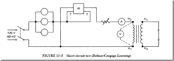
The connections for the short-circuit test are shown in Figure 13–5. A variable resistor is in series with the primary winding. In this way, the current input can be con- trolled. The series resistor is adjusted until the full-load current circulated in both the primary and secondary windings. When the low-side winding of the transformer is short- circuited, only 3% to 5% of the rated primary voltage is required to obtain the full-load current in both windings. This voltage is called the impedance voltage. In other words, the impedance voltage is that voltage required to cause the rated current to flow through the impedances of the primary and secondary windings. The ratio of the impedance voltage to the rated terminal voltage yields the percentage impedance voltage, which is in the range of 3% to 5%.
The wattmeter in Figure 13–5 indicates the total copper losses of the transformer referred to the primary side. The wattmeter reading includes the core losses, which are so small that they can be neglected. The core losses are small because the voltage impressed on the primary winding in this test is very low.
To make the short-circuit test, the core loss of the transformer must be determined using the connections of Figure 13–3A. Using the 50-kVA transformer described in the previous problems, the core loss is 240 W. The readings on the instruments shown in Figure 13–5 will be as follows: a current of 21 A, a power value of 640 W, and a volt- age of 80 V. The value of 640 W represents the total copper losses of the transformer. If the dc ohmic values are used to compute the copper losses in the high- and low-voltage windings, then the total losses are
This value is nearly the same as the constant of 1.10 used to convert the ohmic resistance to the effective resistance for transformers.
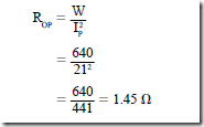
The entire equivalent effective resistance of the transformer referred to the primary side can be found for a wattmeter reading of 640 W and a current of 21 A (at almost full load). When referred to the primary side, this equivalent resistance, R , is
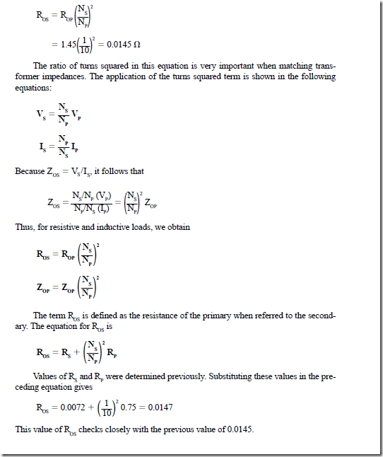
The secondary is the output side of the transformer. Therefore, the entire resistance of the transformer must be referred to the secondary side as an equivalent effective resistance, ROS :
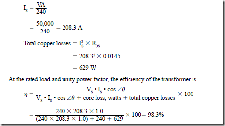
At the rated load, the total copper losses of this transformer are determined as follows. The full-load current is
This value of efficiency, as determined by the short-circuit test, is the same as the efficiency found in problem 5.
Assume that the same transformer is operated at 50% of the rated current capacity to supply a load with a unity power factor. The core loss is the same because the magnetizing flux is the same. However, the copper loss will decrease to one-fourth of its full- load value. Note that this decrease occurs because of the squaring operation in the I2 R formula. The I2 multiplier is only one-fourth of the original value. Use the previous formula and calculate the actual efficiency for this load condition:
If the transformer supplies a load having a power factor other than unity, the output (in watts) will decrease. However, the losses will be the same as those for a unity power factor load. For example, if the 50-kVA transformer supplies the rated output to a load with a power factor of 60% lagging, the efficiency is decreased:


