Three-Phase Systems
INTRODUCTION
Most alternating-current energy is generated by three-phase generators. This energy is then distributed over three-phase transmission systems. The three-phase circuits used are actually three single-phase circuits combined into one circuit having either three or four wires. Single-phase motors and other single-phase loads may be operated from a three- phase circuit.
Unit 1 gave several reasons why three-phase service is preferred to single-phase service for many applications. The rest of this section is a review of these reasons.
1. For given physical sizes of three-phase motors and generators, the horsepower ratings of the motors and the kVA ratings of the generators are larger. A three-phase generator or an induction motor has a capacity that is about 150% that of a single- phase machine having a comparable frame size.
2. The power delivered by a single-phase circuit is pulsating. Figure 2–7 showed the sinusoidal wave patterns of voltage, current, and power for a resistive load. At unity power factor, when the current and the voltage are in phase, the power is zero twice in each cycle. When the current and the voltage are out of phase, the power is zero four times in each cycle. In certain parts of each cycle, the power is negative. Pulsating power is supplied to each of the three single-phase circuits that make up the three-phase system. However, the total power delivered to the balanced three-phase circuit is the same at any instant. As a result, the operating characteristics of three-phase motors and other machines are superior to those of similar single-phase machines.
3. A balanced three-phase, three-wire circuit having the same voltage between the line wires uses only 75% of the copper required for a single-phase, two-wire circuit. Both circuits have the same kVA capacity, voltage rating, length of circuit, and efficiency of transmission.
THREE-PHASE VOLTAGE
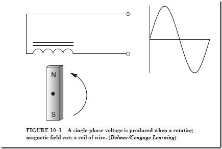
Figure 10-1 illustrates a single-phase alternator. A coil of wire is cut by a rotating magnetic field. Because the magnet contains both north and south magnetic poles, the induced voltage will alternate positive and negative values. The frequency of the ac voltage is determined by the speed of the rotating magnet.
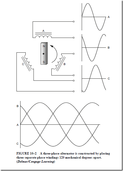
Figure 10-3 illustrates the construction of a three-phase alternator. In this example three separate phase windings are spaced 120 mechanical degrees apart. The rotating magnet will induce voltage into each winding. Due to the placement of the phase wind- ings, the three induced voltages will be 120 electrical degrees apart. This example does not illustrate how the separate phase windings are connected together to form common three-phase connections.
In practice, the coil windings are connected so that only three or four conductors are required to supply a three-phase circuit. There are two standard methods of connecting the
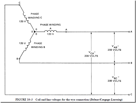
single-phase windings of generators, motors, transformers, and other devices to form three- phase circuits. These methods are known as the wye connection and the delta connection. See Figures 10–3 and 10–10.
PHASE SEQUENCE
The phase sequence, or the phase rotation, is the order in which the three voltages of a three-phase circuit follow one another. For example, phase A, in Figure 10–2, starts to rise in a positive direction at zero electrical degrees. At the same instance in time, phase B is positive and heading in the negative direction while phase C has almost reached its peak negative position. These three voltages are 120 electrical degrees apart. Phase sequence is also expressed as phase rotation. When three-phase voltage is connected to a three-phase motor, a rotating magnetic field is produced inside the motor. The direction of rotation is determined by the phase sequence. The direction of the rotating magnetic field can be reversed by changing any two of the three-phase lines connected to the motor. The phase sequence or phase rotation can also be determined by connecting an oscilloscope to the lines to observe the relative position of the different sine wave voltages or by connecting a phase rotation meter to the three lines.
THE WYE CONNECTION
The wye connection is the most commonly used way of connecting the three single-phase windings of three-phase generators. The three coil or phase windings are placed in the slots of the stationary armature. This armature is called the stator. The
windings are placed so that the three induced voltages are 120 electrical degrees apart. If the ends (marked 0) of each of the phase windings are connected at a common point and the beginnings of the windings (marked A, B, and C) are brought out as the three line leads, the resulting arrangement is the wye connection. Figure 10–3 shows the schematic diagram of a three-phase wye connection.
The Phase Voltages
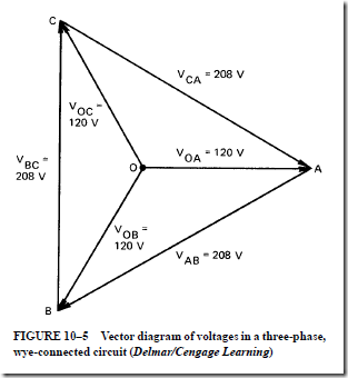
The induced voltage in each phase winding is called the phase voltage. The voltage across the line wires is called the line-to-line voltage. If the voltage induced in each phase winding is 120 V, then the voltage across each pair of line wires is 208 V. Thus, the volt- ages between A and B, B and C, and C and A are all 208 V.
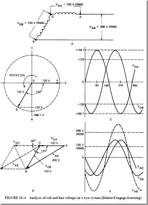
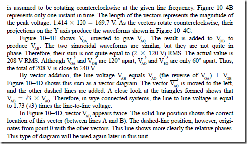
Phase Voltages Are Out of Phase. The two-phase voltages connected together do not add up to 240 V because they are 120° out of phase. Refer to Figure 10–4 during the following discussion of this statement. The phase windings OA and OB are shown in this figure.
Unit 2 stated that the voltages given in ac problems are the effective (RMS) values of the sinusoidally varying voltages. Thus, the actual voltage of phase A (V in Figure 10–4C. This sinusoidal waveform has an effective value of 120 V. V ) is shown is a similar sinusoidal waveform that reaches its maximum value 120 electrical degrees later than does V .
The student should realize that this 120° difference is due to the position of the winding in the generator.
The vector diagram in Figure 10–4B shows that the phase voltages V and V are separated by 120°. As explained in the section on vectors in Unit 3, each voltage vector
is assumed to be rotating counterclockwise at the given line frequency. Figure 10–4B represents only one instant in time. The length of the vectors represents the magnitude of the peak voltage: 1.414 X 120 = 169.7 V. As the vectors rotate counterclockwise, their projections on the Y axis produce the waveforms shown in Figure 10–4C.
Vector Diagram of Voltage
Figure 10–5 is a vector diagram for a three-phase, wye-connected circuit. The diagram shows the three coil voltages and the three line-to-line voltages. Only the voltage relationships for a three-phase circuit have been discussed so far.
What are the current relationships in a three-phase, wye-connected system?
The line current and the phase winding current are the same. These currents are equal because each phase winding is connected in series with one of the three line wires. The following statements give the relationships between the coil and line currents and the voltage in a balanced three-phase wye system.
• The line voltage is equal to �3 times the phase, or coil winding, voltage in a balanced three-phase, wye-connected system.
• The line current values and the phase winding current values are the same in a balanced three-phase, wye-connected system.
Three-Phase, Wye-Connected Circuit
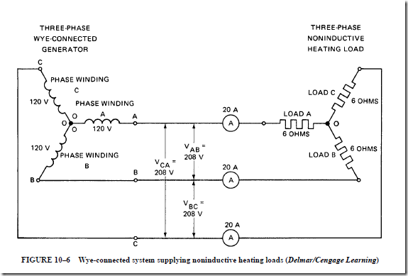
The schematic diagram shown in Figure 10–6 is for a three-phase, wye-connected generator supplying current to a three-phase, noninductive heating load. Kirchhoff’s current law states that the sum of the currents at a junction point in a circuit network is always zero. Therefore, at the source junction (O), the vector sum of the current is zero. Similarly, the vector sum of the three currents at the junction (O) of the heating loads is zero. The currents in the three-phase, three-wire, wye-connected system shown in Figure 10–6 may be unequal because of an unbalanced load. However, the vector sum of the currents at either junction is still zero.
Currents and Voltages in a Wye System
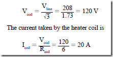
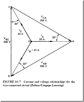
Figure 10–7 is a vector diagram of the currents and voltages for the wye-connected circuit. This circuit operates at a unity power factor. The load shown in Figure 10–6 consists of three noninductive heating elements. Each element has a resistance of 6 n. For a line voltage of 208 V, the voltage across each heater element is
Each 120-V phase voltage in this three-phase generator is in phase with its own coil current of 20 A. However, for a unity power factor, there is a phase angle between the line voltage and the line current, which is also the coil current. This phase angle is 30°, as shown in the vector diagram. Note that the coil voltage (V) is in phase with the coil current, I . Also, the coil voltage, V , is in phase with the current I , and the coil voltage V is in phase with the current I . There is a phase angle of 30 electrical degrees between each of
the following: the line voltage V and the line current I , the line voltage V and the line
current I , and the line voltage V and the line current I .
For resistive loads, the unity power factor causes the line current to lead the line voltage by 30°. Thus, the power factor angle is measured between the coil voltage and the coil current.
Balanced Wye-Connected Motor
Figure 10–8 shows a balanced three-phase, wye-connected motor load supplied from a three-phase, wye-connected source. The angle of lag of each coil current behind its respective coil voltage is 40 electrical degrees. In other words, the phase angle (8) of the power factor is 40°.
The vector diagram in Figure 10–9 shows the relationship between the current and voltage values for the three-phase motor circuit shown in Figure 10–8. The angle 8 (the power factor angle) is the angle between the coil voltage and the coil current.

