SYNCHRONOUS IMPEDANCE (WITH ARMATURE REACTION)
Values of R and X are usually not given for alternators. A method known as the synchronous impedance test can be employed to determine these values. A single-phase alternator is shown in Figure 12–23. To perform this test, the output terminals of the alternator will be shorted by switch S. An ammeter is connected in the alternator circuit to indicate current and a voltmeter is connected across the output terminals to measure voltage.
For discussion purposes, assume that switch S is closed. The field excitation current will be increased until the output current is 150% of the rated full-load current of the alternator. This value of current is recorded. Switch S is then opened and the voltage across the output terminals is recorded. The field excitation current and alternator speed are kept constant. To determine the synchronous impedance of the alternator, the voltage for an open-circuit condition is divided by the current for a short-circuit condition. When the winding is shorted, the voltage is expended in the armature or stator winding. The voltage maintains the current through the impedance of the windings at the operating frequency. The synchronous impedance formula is
PROBLEM 1
Statement of the Problem
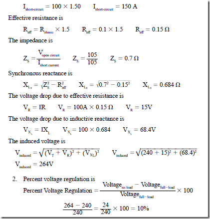
The connection in Figure 12–23 is used to determine the synchronous impedance of a 24-kVA, 240-V, single-phase 60-Hz alternator. The field excitation is adjusted until the ammeter indicates 150% of the rated full-load current. At the same values of field excitation current and speed, switch S is opened. The voltmeter indicates 105 V. The ohmic resistance of the armature or stator winding is measured at 0.1 D. It will also be necessary to assume an effective resistance value for the alternator. Recall that the effective resistance value in an ac circuit can be greater than the measured ohmic value. This is due to factors such as skin effect, eddy current induction into the iron core of the stator winding, and hysteresis losses. Because the windings are inserted deep in slots formed in the core material, the effective resistance could be high. For this example, it will be assumed that the effective resistance will be 1.5 times greater than the measure resistance value.
At unity power factor, determine
1. the induced voltage when the alternator is delivering the rated current.
2. the percent voltage regulation.
Solution
Synchronous Impedance of a Wye-Connected Alternator
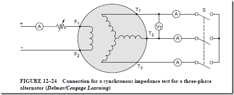
The voltage regulation of a three-phase alternator can also be determined using the synchronous impedance method. Figure 12–24 shows the circuit used to determine the synchronous impedance of a wye-connected ac generator. By closing the three-pole shorting switch (S), the field excitation current is increased gradually until the ammeters indicate 150% of the rated output current. The three ammeter readings are recorded. The three-pole switch is then opened and the voltmeter reading is recorded. The field excitation current and speed are kept constant for both readings. Because the alternator is connected in wye, the voltage of each phase winding is equal to the open-circuit voltage across the line terminals divided by the J3.
The ammeters connected in the lines indicate the phase current values because line current and phase current are the same in a wye connection. The formula for determining the synchronous impedance of each phase winding is
The following problem shows how to determine the voltage regulation of a wye-connected alternator.
PROBLEM 2
Statement of the Problem
A 2100-kVA, 2400-V, three-phase, wye-connected alternator is short-circuited using three ammeters, as shown in Figure 12–24. A voltmeter is connected across two of the line terminals. The field excitation current is increased until each of the three ammeters indicates 150% of the rated full-load current. The switch is opened and the voltmeter indicates an open circuit voltage of 1125 V. The field excitation current and speed are kept constant for both readings. The ohmic resistance is measured at 0.2 D between the line terminals. The ratio of effective resistance to the ohmic resistance is 1.5. Determine
1. the full-load current.
2. the current value for the test.
3. the synchronous impedance.
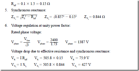
4. the effective resistance.
5. the synchronous reactance.
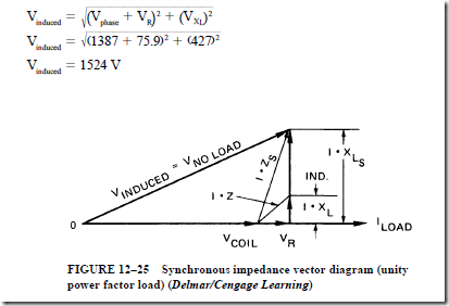
6. the voltage regulation at unity power factor.
7. the voltage regulation at 0.866 lagging power factor.
8. the voltage regulation at 0.866 leading power factor.
Solution
1. Full-load current:
3. Synchronous impedance:
4. Effective resistance – the measured value of 0.2 D is the resistance of two separate phase windings connected in series. Therefore, the resistance of one phase winding is one-half the measured value.
The vector diagram of Figure 12–25 includes the effects of the armature reactance and the armature reaction for an alternator with a unity power factor load. Note the similarity of this vector diagram with the one given in Figure 12–18. Only the armature impedance, reactance, and the effective resistance were considered.
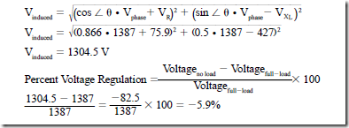
7. Voltage regulation at 0.866 lagging power factor:
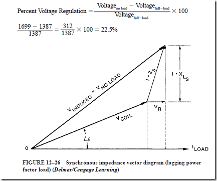
Regardless of the power factor, the full-load current is the same. Therefore, for any power factor load conditions, the voltage loss due to the effective resistance and inductive reactance of the armature or stator winding will be the same. However, the calculated value of the voltage at no load will be different from the value for a unity power factor load. Figure 12–26 and the following calculations show why the voltage at no load is much higher than the voltage at full load with a lagging power factor. This situation means that there is poorer voltage regulation.
To determine the induced voltage at a power factor of 86.6%, or 0.866, it is necessary to determine angle theta. Power factor is the cosine of angle theta. Therefore, angle theta is 30°.
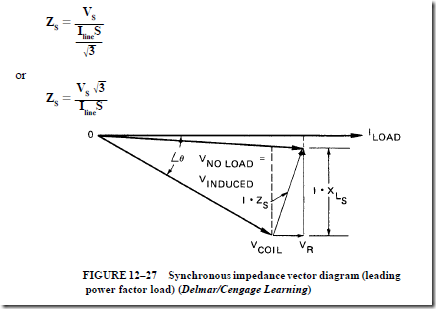
A vector diagram is given in Figure 12–27 for an alternator supplying a load with a leading power factor of 86.6%, or 0.866. In some cases, the voltage at no load may be less than the voltage at full load, depending on the amount of voltage drop due to effective resistance and the voltage drop due to inductive reactance. As a result, a negative value is obtained for the percent voltage regulation. Whenever the percent voltage regulation is negative, the voltage at no load is less than the voltage at full load. In this case, the voltage at no load (V induced) is less than the voltage at full load. Note that in this formula, the voltage drop due to inductive reactance is subtracted from the phase voltage instead of being added to the phase voltage.
Determining Regulation of Three-Phase, Delta-Connected Generator
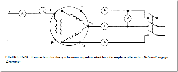
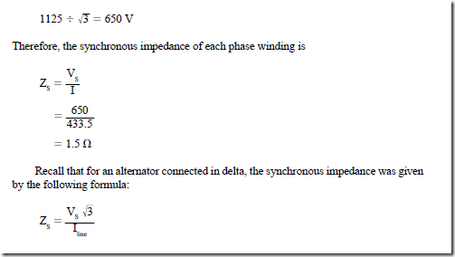
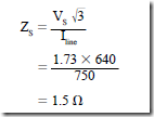
The synchronous impedance test can also be used to find the voltage regulation of a three-phase, delta-connected alternator (Figure 12–28). For a delta connection, the line cur- rent is equal to the phase winding current, multiplied by √-3. In addition, the phase winding voltage and the line voltage are equal. Therefore, the synchronous impedance of each phase winding for a generator connected in delta is
The voltage regulation is to be found for the alternator in the following example. This is the same alternator described in previous examples, except that the phase windings are connected in delta. It is assumed that each phase winding has the following full-load rating: coil current = 289 A and coil voltage = 1387 V.
If each phase winding is loaded to 150% of its rated value, then the coil current is 289 × 1.5 = 433.5 A.
The three-phase windings are connected in delta. Therefore, the line current for a short-circuit condition is 433.5 × J3 = 750 A.
The open-circuit voltage per phase winding is the same for both the wye and delta connections:
This same formula can be used to find the synchronous impedance of an alternator connected in wye:
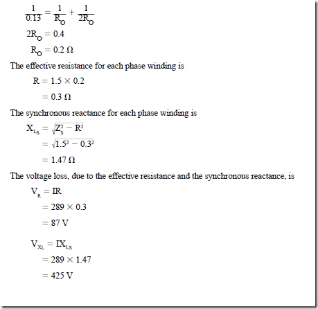
When the ohmic resistance of a delta-connected armature winding is measured across any pair of line terminals, the resulting value includes the resistance of one phase winding in parallel with the other two windings connected in series. For example, when the alternator is connected in wye, the ohmic resistance of each phase winding is 0.2 D. If the three windings are connected in delta, then the ohmic resistance is 0.133 D measured across any pair of line terminals. For both the delta and wye connections, the ohmic resistance of each phase winding is 0.2 D:
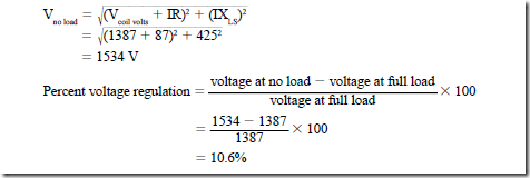
The same procedures are used to determine the voltage at no load and the percent voltage regulation for both delta- and wye-connected alternators. The following calculations give the percent voltage regulation for a delta-connected alternator with a unity power factor load; note that the results are the same as those obtained when the phase windings were connected in wye:


