PARALLEL CIRCUIT WITH BRANCHES CONTAINING R AND XC
Another type of parallel circuit is shown in Figure 8–6. In this circuit, two branches contain noninductive resistance loads and a third branch contains a capacitor. Assuming that the capacitor has negligible resistance, the current in the capacitive branch leads the line voltage by 90 electrical degrees. This means that the line current is the vector sum of the currents in the branches.
PROBLEM 3
Statement of the Problem
The circuit shown in Figure 8–6 contains noninductive resistance and capacitance. For this circuit:
1. Find the current taken by each branch.
2. Construct a vector diagram.
3. Find the total or line current.
4. Find the power taken by the parallel circuit.
5. Find the power factor for the parallel circuit.
6. Find the phase angle.
7. Find the combined impedance.
Solution
1. Branches 1 and 2 contain pure resistance only. The current in each of these branches is in phase with the line voltage.
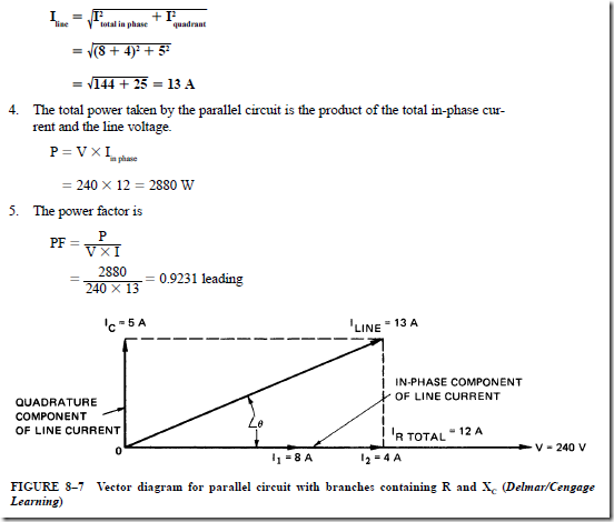
The total in-phase current for the parallel circuit is the sum of the currents in the first two branches: 8 + 4 = 12 A. The quadrature (out-of-phase) component of current is supplied to the capacitor load in branch 3. This current leads the line voltage by 90° and is given by
2. The vector diagram for the circuit is given in Figure 8–7. The two in-phase current values are placed on the line voltage vector. The total in-phase current is 12 A. The current in the capacitive branch is drawn on the vector diagram in a vertical direction from point 0. Thus, the quadrature current leads the line voltage by 90°. The line current is the vector sum of the total in-phase current and the leading quadrature cur- rent. Note that the line current leads the line voltage by the angle fJ. As a result, this parallel circuit operates with a leading power factor.
3. The line current is the hypotenuse of the right triangle shown in Figure 8–7:
6. The line current leads the line voltage by a phase angle (fJ) of 22.6°.
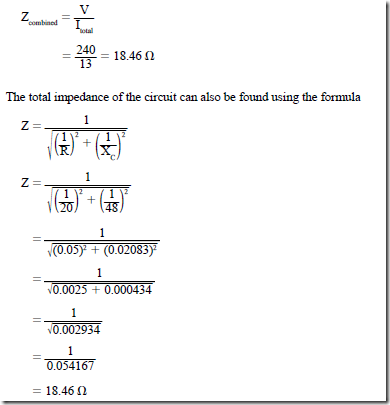
7. The combined impedance (in ohms) of the parallel circuit is
Another formula that can be used to determine the impedance in a circuit that contains both resistance and capacitive reactance connected in parallel is
PARALLEL CIRCUIT WITH BRANCHES CONTAINING R AND Zcoil
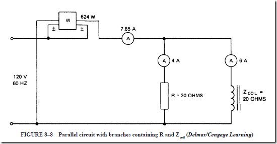
The parallel circuit shown in Figure 8–8 contains two branches. One branch contains a pure resistance of 30 n. The second branch contains a load that has both resistance and inductance. This load is similar to a motor or transformer. The symbol Zcoil is used instead of X because of the coil resistance. It should be noted, however, that the value of Zcoil applies only to the impedance of the coil and should not be confused with the value for the total impedance of the circuit, which is Z total In this circuit, a wattmeter is used to measure the true power of the circuit, and ammeters are used to measure the total current flow and the current flow through each branch. In this circuit, the current will lag the voltage by some value less than 90°.
PROBLEM 4
Statement of the Problem
For the circuit in Figure 8–8, the following items are to be determined:
1. The current taken by each branch
2. The resistance of the coil
3. The power factor of the coil
4. The in-phase component of current in the coil
5. The quadrature component of current in the coil
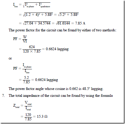
6. Total impedance of the circuit
Draw a vector diagram for the circuit, and determine (1) the line current and (2) the circuit power factor.
Solution
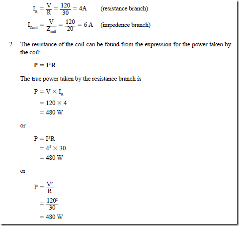
1. The current in each branch of the circuit is given by Ohm’s law:
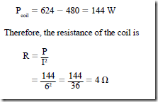
The true power taken by the resistance branch is subtracted from the total power taken by the parallel circuit to find the power taken by the coil. Thus, the actual power used in this coil is coil = 624 – 480 = 144 W Therefore, the resistance of the coil is
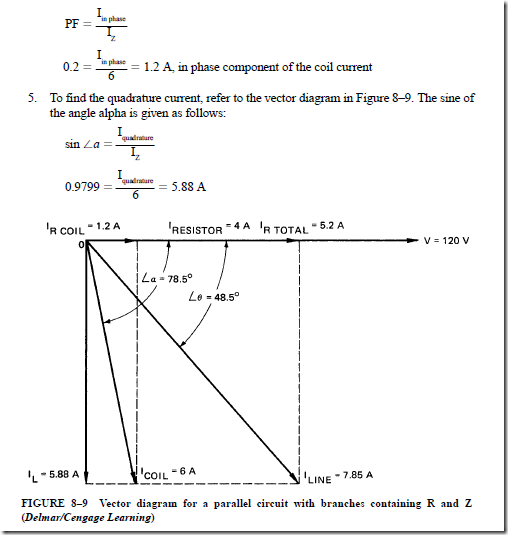
3. To find the power factor of the coil, it is assumed that the coil is a series circuit containing resistance and inductive reactance. For this case, the power factor is expressed as follows:
For a power factor of 0.20, the coil current lags behind the line voltage by an angle of 78.5°.
4. The 6-A current in the coil can be resolved into two components. One component is the in-phase current. The second component, or quadrature current, lags the line voltage by 90° because of the inductive reactance in this branch.
6. The vector diagram for the circuit is shown in Figure 8–9. The in-phase current for the coil (1.2 A) is placed on the line voltage vector. The quadrature component of the current (5.88 A) is in a downward direction at an angle of 90° to the line voltage. The vector sum of these components is the current taken by the coil (6 A). The phase angle between the coil current and the line voltage is 78.5°. The current taken by the resistance branch (4 A) is added to the in-phase current of the coil circuit. Thus, the total in-phase current is 5.2 A. The circuit must be supplied with 5.2 A in phase with the line voltage and a quadrature current of 5.88 A lagging the line voltage by 90°. The vector sum of these two components is the line current (7.85 A). The line current lags the line voltage by 48.5°. The total line current is the hypotenuse of a right triangle in the vector diagram of Figure 8–9:


