Capacitors and RC Time Constants
INTRODUCTION
Direct Current Fundamentals explained how a material is a conductor or an insulator because of its atomic structure. It was stated that electrons are loosely held in the outer electron shells of each atom of a good conductor such as copper. Only a small force is required to dislodge these electrons. Good conductors have many free electrons in their structure.
A characteristic of insulating materials is that their electrons are firmly held in the electron shells of each atom of the material. A great deal of force is required to remove these electrons. Insulating materials have few free electrons in their structure.
The Elementary Capacitor
If an insulating material, known as a dielectric, is placed between two plates of a con- ducting material, the resulting assembly is an elementary capacitor.
In Figure 5–1, a simple capacitor is shown to consist of two metal plates separated from each other by a thickness of dielectric. Under normal conditions, with the capacitor deenergized, the electrons in the dielectric revolve in circular orbits around the nucleus of each atom.
Charging the Capacitor. The capacitor is shown connected to a dc voltage source in Figure 5–2. Electrons will flow from the negative side of the source to plate 2 and from plate 1 back to the source. This movement of electrons from negative to positive is the normal direction of electron flow.
Electrons will continue to move until the potential difference across the two metal plates is equal to the dc source voltage. When the potential and the voltage are the same, the flow will stop. There will be almost no flow of electrons through the dielectric (insulating) material between the plates. There will be a surplus of electrons on plate 2 and a deficiency of electrons on plate 1. The electrons in the atoms of the dielectric material will be attracted toward the positive plate and repelled from the negative plate. However, these electrons cannot flow from plate 1 to plate 2 because the electrons in a good dielectric material are firmly held in each atom.
Thus, the forces acting on the electrons cause their orbits in each atom in the dielectric to be distorted. As shown in Figure 5–3, the orbits form elliptical patterns.
The capacitor in Figure 5–3 is completely charged. The voltage across the capacitor plates is equal to the dc source voltage. Therefore, there is no electron flow. To simplify the figures, only three atoms are shown. In an actual capacitor, there are millions of atoms with distorted orbits in the dielectric.
If the capacitor is disconnected from the dc supply, the surplus electrons on the nega- tive plate are held to this plate by the attraction of the positive charge of the other plate. In other words, an electrostatic field effect is created by the charged plates. This effect maintains the distortion of the electron orbits in the atoms of the dielectric. The atomic distortion of the dielectric is an indication of the electrical energy stored in the capacitor.
If the voltage applied to the capacitor is too large, the electrons in the atoms of the dielectric will be pulled from their orbits. The insulating ability of the dielectric breaks down, and the energy stored in the capacitor is released. In the case of a solid dielectric material, such a breakdown destroys its usefulness and a shorted capacitor results.
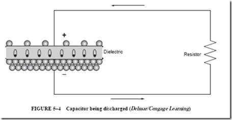
Discharging the Capacitor. A resistor is now connected across the capacitor as shown in Figure 5–4. The capacitor discharges through the conducting resistor. Electrons on the negatively charged plate (plate 2) will leave the plate and will flow toward plate 1 through the resistor. This electron flow continues until they are distributed equally in the circuit. Then the flow of electrons stops. While the electrons flow, the electrical energy stored in the electrostatic field is being released from the dielectric of the capacitor.
As the electrons flow from the negatively charged plate, a change takes place in the electron orbits of each atom of the dielectric. That is, the orbits change from the distorted elliptical pattern (Figure 5–4) to their normal circular pattern (Figure 5–5).
Leakage Current
In theory, it should be possible for a capacitor to remain charged forever. In actual practice, however, it cannot. No dielectric is a perfect insulator, and over a period of time electrons will eventually move through the dielectric from the negative plate to the positive plate, causing the capacitor to discharge (Figure 5–6). This current flow through the dielectric is called leakage current and is proportional to the resistance of the dielectric and the charge across the plates. If the dielectric of a capacitor becomes weak, it will permit an excessive amount of leakage current to flow. A capacitor in this condition is referred to as a leaky capacitor.
CAPACITANCE
The Meaning of Capacitance
A capacitor can store electrical energy. It can also return this energy to an electric circuit. It is important to understand what the term capacitance actually means. Capacitance is the property of a circuit, or circuit component, that allows it to store electrical energy in electrostatic form.
The Measurement of Capacitance
Circuit components other than capacitors may create a capacitance effect. For example, when two wires of a circuit are separated by air, they will act as a capacitor. Also, adjacent turns of a coil winding, which are separated only by the insulation of the wire,
will have some capacitance effect. The standard unit of measurement for capacitance is the farad. This unit of measurement is defined as follows:
A capacitor has a capacitance of one farad when a change of one volt across its plates results in a charge movement of one coulomb.
The farad is too large a unit for a typical capacitor. A smaller unit, known as a microfarad, is commonly used. The microfarad is equal to 1 –: 1,000,000, or 10-6 farad. The letter symbol for the farad is F. The microfarad is indicated by the symbol p,F, where p, is the Greek letter mu.
Electronic circuits often require very small capacitors. In such cases, even the micro- farad is too large. A smaller unit of capacitance measurement is required. This unit is the picofarad. One picofarad is equal to 1 –: 1,000,000th of a microfarad, or 10-12 farad. The letter symbol for the picofarad is pF.
The capacitance of a capacitor can be increased by any of the following factors:
• Increasing the plate area, resulting in an increase in the area of the dielectric under stress
• Moving the metal plates closer together, resulting in a decrease in the thickness of the dielectric
• Using a dielectric with a higher dielectric constant
The Charge of a Capacitor
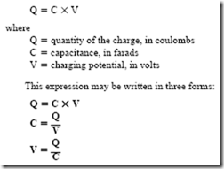
For a given applied voltage, the charge on the plates of a capacitor is directly proportional to the capacitance of the capacitor. The charge is measured in coulombs and is directly proportional to the charging voltage. If the charge on the plates is directly proportional to both the capacitance and the impressed voltage, then the charge is expressed as follows:
As an example of the use of this formula, assume that a capacitor takes a charge of 0.005 coulomb (C) when connected across a 100-V dc source. Determine the capacitance of the capacitor in microfarads:


