CAPACITORS IN SERIES
When capacitors are connected in series, the dielectrics of the individual capacitors are connected one after the other to form a single circuit path. This arrangement is equivalent to increasing the thickness of the dielectric of one capacitor. This means that the total capacitance of the circuit is less than the capacitance of any individual capacitor.
When capacitors are charged in a series circuit, the same number of electrons flow to each capacitor. As a result, each capacitor has the same charge (Q) in coulombs.
For example, Figure 5–9 shows three capacitors connected in series across a line volt- age (V). The capacitors have the same ratings as in Figure 5–8 for a parallel circuit. It can be shown that the total capacitance of the capacitors connected in series is less than the capacitance of any one capacitor.
The voltage across the series circuit is
The charge in coulombs on each capacitor is the same:
The formulas for total capacitance can be used only when all of the values are in the same unit of capacitance measurement, either microfarads or picofarads. If some of the capacitors in a circuit are rated in microfarads and the rest are rated in picofarads, then some values must be changed so that all of the values are expressed in the same unit of measurement before the total capacitance is found.
The total capacitance can also be determined using the product-over-sum formula:
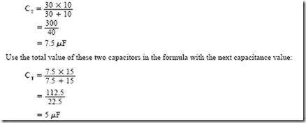
In the example above, three capacitors having values of 30 p,F, 10 p,F, and 15 p,F are connected in series. The total capacitance can be determined by substituting two values at a time and then using that answer with the next capacitance value:
This procedure can be followed until all series capacitance values have been employed.
A third formula for determining the total capacitance of capacitors connected in series can be used only when all the capacitance values are the same. Assume that four capacitors, each having a value of 60 p,F, are connected in series. The total capacitance can be determined by dividing the capacitance value of one capacitor by the number of capacitors.
CAPACITORS IN NETWORK SYSTEMS
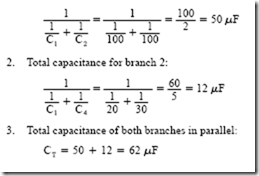
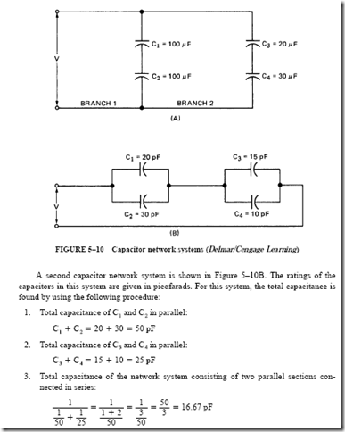
Capacitors can also be connected in network systems where the total capacitance must be determined. Figure 5–10 shows two capacitor network systems. To obtain the total capacitance of the capacitor network system in Figure 5–10A, the following procedure is used:
1. Total capacitance for branch 1:
ENERGY IN A CAPACITOR
It was shown at the beginning of this unit that a capacitor will store electrical energy. The amount of energy stored in a capacitor, in joules or watt-seconds, can be determined as follows:
Thus, one-half the charge in coulombs times the charging potential in volts yields the energy in joules stored in the capacitor. Recall that Q = C X V. Therefore, C X V may be substituted for Q in the previous formula with the result that
For example, a 50-p,F capacitor is connected across a 300-V dc source. It is required to find the energy in watt-seconds stored in this capacitor:
RC TIME CONSTANTS
Direct Current Fundamentals showed that the intensity of electron flow per second in amperes is expressed by amperes = coulombs divided by seconds (I = Q/t). Also, the quantity of electrons in coulombs is given by coulombs = amperes times seconds (Q = I X t). For a capacitor, the charge in coulombs on the plates is a function of the intensity of current (amperes) and the time (seconds) of charging. As the value of the current increases, less time is required to charge the capacitor fully.
Recall that the voltage across the plates of a capacitor equals the line voltage when the capacitor is fully charged. The charging time for a given capacitor depends on the charging current. Thus, the time required for a given voltage to build up across the capacitor can be controlled by increasing or decreasing the charging current. The charging cur- rent can be controlled by placing a series assembly of a resistor and a capacitor across the charging potential. In other words, this current controls the time that must elapse before a given voltage exists across the capacitor terminals.
Charging the Capacitor
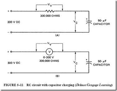
The circuit shown in Figure 5–11A consists of a 50-p,F capacitor connected in series with a resistor across a 300-V dc supply. In Figure 5–11B, the resistor consists of a dc voltmeter having a scale range of 300 V and a resistance of 1000 D/V. Thus, the resistance of this voltmeter is 300,000 D. At the instant the circuit is energized, the voltmeter needle swings to a full-scale reading. Such a value indicates that all of the line voltage is across the terminals of the voltmeter. (This voltmeter acts like a 300,000-D series resistor.) The voltage across the capacitor at this same instant is zero.
The equation for the voltage in the series circuit in Figure 5–11B is
where VC is the voltage across the capacitor and VV is the voltage across the voltmeter. The applied voltage (V) is constant. This means that as the voltage across the capacitor (V ) increases, the voltage across the voltmeter (V ) must decrease. As the voltage across the capacitor approaches the applied voltage (V), the current in the circuit approaches zero. In effect, the voltage across the capacitor is a backward voltage that reduces the current flow. As the current approaches zero, the voltage across the voltmeter approaches zero.
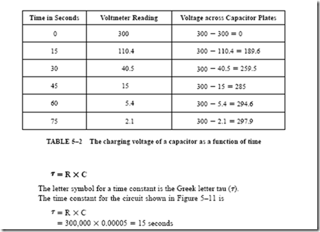
Plotting the Charging of the Capacitor. A curve can be plotted of the rising voltage across the capacitor plates. For the circuit of Figure 5–11B, voltmeter readings are taken at 15-s intervals. In each case, the reading is subtracted from the fixed line voltage (V). As a result, the voltage across the plates of the capacitor can be determined as the capacitor charges. Table 5–2 lists the voltage across the capacitor plates at 15-s intervals, as obtained by this method. At zero seconds, note that the capacitor is completely discharged. At the end of 75 s, the voltage across the capacitor plates has almost reached the value of the line voltage.
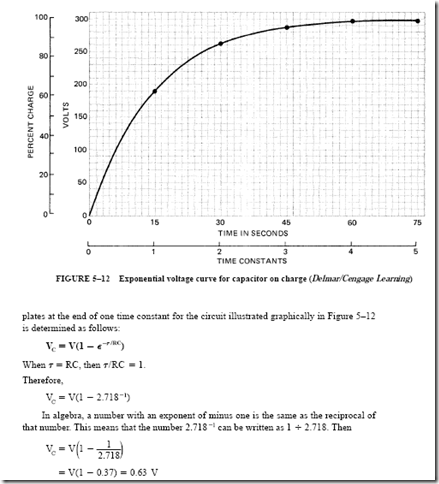
Drawing the Exponential Charging Curve. The data in Table 5–2 are plotted in Figure 5–12 to form a curve of the rising voltage across the capacitor plates for the interval of 75 s.
Note in the figure that the horizontal axis of the curve is marked both in time constants and time in seconds. The term time constant is defined as follows:
One time constant is the time, in seconds, required for a completely discharged capacitor to charge to 63.2% of the source voltage. This charging time is equal to the product of the resistance in ohms and the capacitance in farads:
Refer to Figure 5–12 and note that the 15-s mark on the horizontal scale corresponds to the mark for one time constant. From the definition of a time constant, the voltage across the capacitor plates in an RC series circuit is 63.2% of the impressed voltage at the end of one time constant. For this circuit, then, the voltage across the capacitor plates at the end of one time constant is 300 X 0.632 = 189 V.
Formula for an Exponential Curve. The curve shown in Figure 5–12 is known as an exponential curve. The voltage curve for a series RC circuit is expressed by the following mathematical formula
The quantity (1 – E–T /RC) is called an exponential operator and is considered to be an operator on the voltage (V).
The formula for V may be used to find the percentage of the impressed voltage on the capacitor plates at the end of one time constant, two time constants, or any desired number of time constants. For example, the percentage of the impressed voltage on the capacitor
This calculation shows that the voltage across the capacitor plates at the end of one time constant is equal to 63.2% of the impressed voltage. For the RC series circuit of Figure 5–11, the actual voltage on the capacitor plates at the end of one time constant is
Recall that this same value was determined graphically in Figure 5–12. To find the percentage of the impressed voltage across the capacitor plates at the end of two time constants, the calculations are as follows:
In this problem, the exponent T/RC is equal to two (two time constants are involved).
A number with a negative exponent is the same as the reciprocal of that number to the given power. Because E-2 is the same as 1 ÷ 2.7182, we obtain
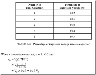
These calculations can be repeated for any number of time constants. The resulting percentages are given in Table 5–3 for five time constants.
Based on the information given in Table 5–3, it is assumed that the capacitor is fully charged at the end of five time constants.
Discharging the Capacitor
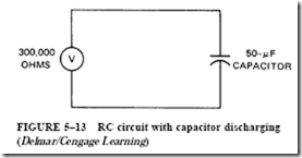
When a capacitor is discharged through a resistor, the amount of time required depends on the value of the resistor. The 50-p,F capacitor shown in Figure 5–13 is assumed to be completely charged at 300 V. This capacitor is to be discharged through the 300,000-D resistance of a voltmeter.
As a capacitor discharges through a resistor during one time constant, the volt- age across the capacitor decreases to 37% of its value when the capacitor was fully charged. To determine capacitor voltages on discharge, the following exponential formula is used
Plotting the Voltage Curve for a Capacitor on Discharge. Assume that the fully charged capacitor has a potential difference of 300 V across its terminals. When the capacitor is discharged, the voltage across the terminals at the end of one time constant is
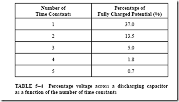
This calculation can be repeated for any number of time constants. The results are summarized in Table 5–4, which lists the percentage of voltage on the plates of a discharging capacitor for each of five time constants.
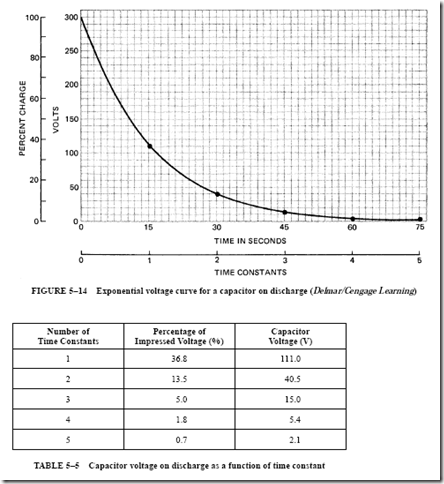
By plotting the values given in Table 5–4, an exponential voltage curve is obtained for the discharge of the 50-p,F capacitor connected across the 300,000-D voltmeter (Figure 5–14). The voltmeter serves as the discharge resistor. It also measures the decreasing voltage across the capacitor plates. The curve shows that the capacitor voltage decreases from 300 V
to a value near zero. Table 5–5 shows the percentage of voltage and the actual voltage during the capacitor discharge for each of five time constants.
Current Relationships of a Capacitor
The study of RC circuits to this point has been based on the voltage relationships across the terminals of a capacitor. However, it is also important to study the current relationships for a capacitor when it is charging and discharging.
When a completely discharged capacitor is connected in series with a current-lim- iting resistor across a dc source, the initial current at the instant the circuit is energized is determined by I = V –: R. The capacitor dielectric offers no opposition to the current when the capacitor is discharged. As the charge on the capacitor plates increases, a volt- age develops.
This voltage increases with time, as shown in Figure 5–12, until its value is equal to the line voltage. As the voltage increases, the current decreases following an exponential curve. When the voltage across the capacitor plates equals the line voltage, the charging current becomes zero.
If the same capacitor is discharged through a resistor, the direction of electron flow is reversed. At the instant the fully charged capacitor is connected to the resistor, the initial current is equal to V –: R. As the voltage across the capacitor terminals decreases following an exponential curve, the current also decreases in a similar manner.
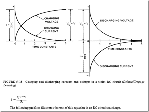
Charge and Discharge Curves. Figure 5–15 shows the charge and discharge curves for current and voltage for an RC circuit. During charging, the charge current decreases as the potential across the capacitor plates increases. Both curves follow an exponential pattern. When the capacitor is discharged, the current decreases exponentially from its initial value to zero. The curve for the current on discharge is below the zero reference line defined by Ohm’s law. This location means that the direction of current in the circuit is reversed when the capacitor is discharging. Note that the discharging voltage curve looks like the charging current curve. Likewise, the discharging current curve looks like the charging voltage curve.
At the beginning of either a charge period or a discharge period, the initial current is given by Ohm’s law. To find the current after a given number of time periods, for either charge or discharge, a modified form of Ohm’s law is required.
PROBLEM 2
Statement of the Problem
Refer to the RC circuit shown in Figure 5–11. Determine
1. the initial charge current at the instant the circuit is energized.
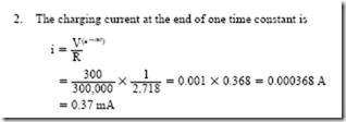
2. the current at the end of one time constant.
Solution
1. At the instant the circuit is energized, the charging current is limited by the resistance of the voltmeter alone. The initial current is


