10–6 VOLTAGE DROP ON A LINE
Why do the lights in a house dim when a motor starts? The question is answered by Ohm’s law and the use of the series circuit principle.
The sum of individual voltages equals the total applied voltage.
Assume that each wire leading to the house, as illustrated in Figure 10–10A, has 0.5-ohm resistance and that lamps in the house cause a 2-ampere current in the line. We then have a series circuit and can calculate the voltage at the house.
Each line wire is, in effect, a 0.5-ohm resistor with 2 amperes through it.
which is the potential energy used to maintain the 2-ampere current in the 0.5-ohm resistance of the wire. One volt is used on each wire, since the potential difference between the wires at the house is equal to 120 2 2 or 118 volts, as shown in Figure 10–10B.
If a motor is turned on so that the current in the line becomes 20 amperes instead of 2 amperes, more voltage will be required to maintain the current in the line leading to the house.
E = IR
E = 20 x 0.5
E = 10 V for each wire
Therefore, subtracting 20 volts from 120 volts gives 100 volts delivered at the house, as shown in Figure 10–10C.
With 2 amperes in the line, the voltage at the house is 118 volts; and with 20 amperes in the line, the voltage at the house is 100 volts. Lighting in the house is dimmer on 100 volts than on 118 volts, since the decreased voltage means that there is less current in the lamps. This 2-volt or 20-volt loss is called the voltage drop on the line. According to Ohm’s law, this voltage depends on the resistance of the line and the current in the line (ED = IL x RL).
EXAMPLE 10–7
Given: A certain electric motor requires at least 12 amperes at 110 volts to operate properly, as shown in Figure 10–11, and the motor is to be used 500 feet from a 120-volt power line.
Find: The size copper wire needed for the 500-foot extension.
Solution
Since the source is 120 volts and 110 volts must be delivered to the motor, the difference, 10 volts, can be used by the wire when the current is 12 amperes. Since E and I are known, we can find the resistance of the extension wires.
R =E/I
R = 0.83 Ω
(These wires are a resistance in series with the motor. Applying Ohm’s law, we used the 10 volts to find the resistance of the wire that is responsible for the 10-volt potential difference.)
The wire size can now be found from tables. (See Figure A–2 in the Appendix: American Wire Gauge.) The 500-foot extension requires 1,000 feet of wire with no
more than 0.83 ohms of resistance. Using the “Ohms per 1,000 ft.” column in Figure A–2, we find that the closest wire size is #9. (If #9 copper wire were not available, then the extension could be made of #8 copper wire.)
10–7 VOLTAGE AT AN OPEN ELEMENT
In Figure 10–12 there were seven lamps in the series circuit, but one lamp has been removed. How much voltage, if any, exists across the open socket?
One way of arriving at the answer is to consider how much of the 220-volt source is being used on each of the six remaining lamps, using E 5 IR. The current in each lamp is zero. As a result, each lamp has 0 volts across it; therefore, the entire 220-volt potential appears at the open socket.
The same reasoning applies to voltage at an open switch. The pressure is there, even though it may not be causing any current.
10–8 SERIES CIRCUITS AS VOLTAGE DIVIDERS
When series circuits are used for the purpose of obtaining different voltages from one voltage source, they are known as voltage dividers. The principle of voltage division was implied earlier, in Section 10–3, where it was stated that “. . . voltage drops are proportional to the values of the resistors.” In other words, voltage dividers are series circuits in which the source voltage is divided among the resistors proportionally to their ohmic values.
The six circuit diagrams shown in Figure 10–13 will help clarify this point, especially if you make the effort to confirm the mathematical accuracy by using Ohm’s law.
In some applications, voltage division is achieved by means of potentiometers. You may wish to refresh your memory on that subject by rereading Section 7–12, dealing with variable resistors.
Remember, a potentiometer is a three-terminal device having the same effect as the two-resistor circuit in Figure 10–13A. In fact, the movable contact of the potentiometer divides the resistance element into two series-connected resistors. By varying the setting of the movable contact, any voltage drop from zero to maximum can be obtained, as shown in Figure 10–14.
10-9 THE GENERAL VOLTAGE DIVIDER FORMULA
A common method for determining the voltage drop across series elements is to use the general voltage divider formula. Since the current flow through a series circuit is the same at all points in the circuit, the voltage drop across any particular resistance is equal to the total circuit current times the value of that resistor:
The voltage drop across any series component (EX) can be determined by substituting the value of RX for the resistance value of any component when the source voltage and total resistance are known.
A series circuit containing three resistors is connected to a 48-volt source. Resistor R1 has a value of 400 ohms, R2 a value of 600 ohms, and R3 a value of 280 ohms. What is the voltage drop across each resistor?
Solution
Find the total resistance of the circuit.
10–10 POLARITY CONSIDERATIONS
In discussing the voltage distribution of a circuit, it is not good enough to merely refer to the magnitude of the voltages. Equal consideration should be given to the polarity of the voltages.
To illustrate this point, let us have another look at a voltage divider circuit in which we have identified the terminal points of the resistors with letters, as shown in Figure 10–15.
To determine the polarity of a voltage drop, we simply consider the direction of the current. Remember, electrons move from negative to positive, as indicated by the arrows in our drawing. Since the electrons flow from point A toward point B, it follows that point A is negative with respect to point B. (We could have said, instead, that point B is positive with respect to point A.) Similarly, point B is negative with respect to point C (or point C is positive with respect to point B).
Do not be confused by the two polarity markings (1 and 2) at points B, C, and D. Some students may wonder how any given point can be assigned both positive and negative
 markings at the same time. This simply depends on your reference point. Point C is positive with respect to point B, but it is negative with respect to point D. This is somewhat analogous to describing someone’s age. A person can be described as being young and old at the same time. Compared to your grandfather, you are young; but compared to your baby brother, you are old.
10–11 GROUND AS A REFERENCE POINT
The concept of a reference point is important in describing not only polarity markings but voltage levels as well. In electrical theory such reference points are often called ground, regardless of whether or not they are actually connected to the earth. Automobiles, for instance, are said to have a negative ground. That simply means that the chassis, connected to the negative terminal of the battery, is the common reference point. But certainly the car is not grounded to the earth. If anything, it is well insulated from the earth by its rubber tires.
Two graphic symbols are used in schematics to denote a ground, as shown in Figure 10–16. The first, Figure 10–16A, is used to describe a chassis ground. Let us employ that symbol to denote a reference point in the voltage divider circuit of Figure 10–15.
We are going to place this reference point first on point A, then on point B, then on to points C, D, and E. The schematics shown in Figure 10–17 will show how the voltage levels on each point change with every change of the reference ground.
Be sure to study these drawings to gain understanding of this important principle. The same concept will be presented in the following section, as well as in Chapter 12.
10–12 VOLTAGE SOURCES IN SERIES
Cells and other voltage sources are often connected in series to obtain higher volt- ages. The voltage produced by several cells connected in series is the total of the individual cell voltages; see Figure 10–18. This method of connecting voltage sources is known as series-aiding. Note that with this method, the positive pole of one source always connects with the negative pole of another source. A familiar example of this is the loading of a flashlight with multiple dry cells.
Consider, by contrast, two voltage sources interconnected with identical poles, as shown in Figure 10–19. Such connections are known as series-opposing. When voltage sources are connected like this, their voltages subtract from one another. If the individual source voltages are equal, their combined output will equal 0 volts, as shown in Figure 10–19A.
If the individual source voltages are of different magnitude, their net difference will represent the output voltage, with the larger of the two determining the polarity of the output. (Compare Figures 10–19B and C.)
• In series circuits there is only one path for the current.
• In series circuits the current is the same for all components.
• In series circuits the sum of all voltage drops is equal to the applied voltage.
• In series circuits the total circuit resistance is equal to the sum of all the individual resistors.
• In series circuits the total circuit power is equal to the sum of all the individual resistors’ power dissipation.
• Long power lines supplying a load represent resistors in series with the load causing a voltage drop in the line.
• When one resistor element in a series circuit opens up, the source voltage will appear
across its terminals.
• Series circuits may be considered voltage dividers.
• Voltage division is achieved proportionally to the values of the resistors.
• The general voltage divider formula is used to determine the voltage drop across series elements
• The polarity of voltage drops is negative at the point where the electron current enters the resistor and positive where the current exits.
• The word ground denotes a common reference point.
• Voltage sources may be connected series-aiding or series-opposing.
Achievement Review
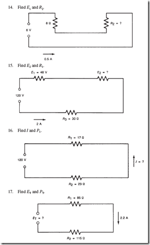
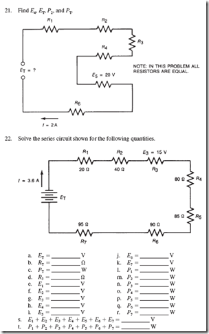
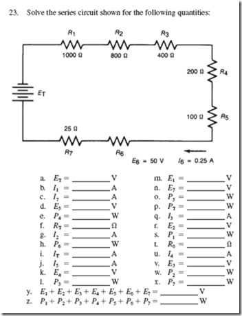
Note: For each problem, draw a circuit diagram to gain practice in schematic work and to aid in visualizing each problem. All answers must include units of measurement.
1. In a television receiver, two resistors are in series. The first resistor (R1) has a voltage drop of 200 volts across it. The second resistor (R2) has a drop of 50 volts across it. Current in the circuit is 20 milliamperes (0.02 A). What is the value of each resistor? What is the total resistance?
2. In question 1, what wattage is dissipated by each resistor?
3. Across a 300-volt power supply in an electronic device there are four resistors in series. Resistor values are 20,000, 50,000, 500, and 4,500 ohms. What is the current, in milliamperes, that flows through this network?
4. In a radio there are three resistors in series: R1 has a 1.5-volt drop across it; R2 has a 3-volt drop across it; and R3 has a 0.6-volt drop across it. R3 is 20 ohms. What is the current in the circuit, and what are the resistance values of R1 and R2?
5. Consider a barn located a considerable distance from a farmhouse. The two wires supplying the power to the barn have a resistance of 0.3 ohm each. The resistance of these wires forms a series circuit with the load (machinery) in the barn. The voltage at the farmhouse is 120 volts. How many volts will be avail- able at the barn when 20 amperes is supplied?
6. Explain how the answer would change in question 5 if the current were increased to 35 amperes. Specifically, what effect would this have on the machinery to be operated in the barn?
7. Two resistors are connected in series across a 24-volt power supply. A voltage drop of 9 volts can be measured across the first resistor. The current through the second resistor is 1.5 amperes. What are the values of the two resistors?
8. Vacuum tubes such as the ones used in older radios or TVs require different volt- ages for their heaters. An efficient method of connecting such heaters is in a series configuration, providing that all tubes require the same heater current. Consider the following four tubes connected in such a manner to a 120-volt supply:
Tube #1 requires 25 V/0.3 A
Tube #2 requires 12 V/0.3 A
Tube #3 requires 6 V/0.3 A
Tube #4 requires 12 V/0.3 A
If the tubes were to be connected to a 120-volt circuit, an additional series-drop- ping resistor would be needed to compensate for the difference in voltages. What must be the ohms and wattage rating of such a resistor?
9. A motor rated for use on a 230-volt line can generally tolerate 7% voltage fluctuation.
a. What is the lowest voltage it will tolerate?
b. Assuming that such a motor will draw 12 amperes when run at 214 volts, if the motor is located 800 feet away from the power source, what size wire must be installed? Let us find out! First, draw a simple schematic diagram like this.
Note that the resistances of the wires are connected in series with the motor, dropping a voltage along the way that is lost to the motor.
c. How much is the voltage drop in the wire?
d. Using this answer (and Ohm’s law) find the maximum resistance permissible
in the wire.
e. How many feet of wire are needed for this installation?
f. Use the preceding two answers to compute the number of ohms per 1,000 feet.
g. Now consult your wire table to find the proper wire size for this installation.
10. An advertising sign is to be constructed with low-voltage lightbulbs rated at 6 V/25 W. The bulbs will be connected to a source of 114 volts.
a. How many lamps should be used?
b. If only 16 bulbs were used, how much voltage would each lamp receive?
c. What effect will this have on the current?
d. How will this affect the life span of the bulb?
By contrast, if 20 or more lamps were to be used, what effect would this have on
e. The light intensity?
f. The power consumption?
11. Find ET and P2.


