Scaling amplifier
One final type of summing amplifier is the SCALING AMPLIFIER. This circuit multiplies each input by a factor (the factor is determined by circuit design) and then adds these values together. The factor that is used to multiply each input is determined by the ratio of the feedback resistor to the input resistor. For example, you could design a circuit that would produce the following output from three inputs (E1, E2, E3):
![]()
Using input resistors R1 for input number one (E1), R2 for input number two (E2), R3 for input number three (E3), and R4 for the feedback resistor, you could calculate the values for the resistors:

Any resistors that will provide the ratios shown above could be used. If the feedback resistor (R4) is a 12-kilohm resistor, the values of the other resistors would be: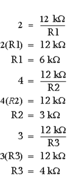
Figure 3-24 is the schematic diagram of a scaling amplifier with the values calculated above.
Figure 3-24. – Scaling amplifier.

To see if the circuit will produce the desired output, calculate the currents and voltages as done for the previous circuits.
With:

Calculate the current for each input:

Calculate the output voltage:
You have now seen how an operational amplifier can be used in a circuit as an adder, a summing amplifier, and a scaling amplifier.
Difference Amplifier (Subtractor) A difference amplifier will produce an output based on the difference between the input signals. The subtractor circuit shown in figure 3-25 will produce the following output:
![]()
Figure 3-25. – Subtractor circuit.

Normally, difference amplifier circuits have the ratio of the inverting input resistor to the feedback resistor equal to the ratio of the noninverting input resistors. In other words, for figure 3-25:
and, by inverting both sides:
Back
Home
Up
Next
Difference amplifier
For ease of explanation, in the circuit shown in figure 3-25 all the resistors have a value of 1 kilohm, but any value could be used as long as the above ratio is true. For a subtractor circuit, the values of R1 and R3 must also be equal, and therefore, the values of R2 and R4 must be equal. It is NOT necessary that the value of R1 equal the value of R2.
Using figure 3-25, assume that the input signals are:

To check this output, first compute the value of R2 plus R4:![]()
With this value, compute the current through R2 (IR2):  (indicating current flow from left to right)
Next, compute the voltage drop across R2 (ER2):

Then compute the voltage at point B:

Since point B and point A will be at the same potential in an operational amplifier:![]()
Now compute the voltage developed by R1 (ER1):
Compute the current through R1 (IR1):
Compute the voltage developed by R3 (ER3):
Add this to the voltage at point A to compute the output voltage (E out):

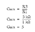
As you can see, the circuit shown in figure 3-25 functions as a subtractor. But just as an adder is only one kind of summing amplifier, a subtractor is only one kind of difference amplifier. A difference amplifier can amplify the difference between two signals. For example, with two inputs (E1 and E2) and a gain of five, a difference amplifier will produce an output signal which is:![]()
The difference amplifier that will produce that output is shown in figure 3-26. Notice that this circuit is the same as the subtractor shown in figure 3-25 except for the values of R3 and R4. The gain of this difference amplifier is:
Figure 3-26. – Difference amplifier.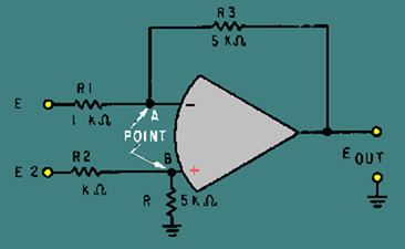
Then, for a difference amplifier:
With the same inputs that were used for the subtractor, (E1 = + 3 V; E2 = + 12 V) the output of the difference amplifier should be five times the output of the subtractor (Eout = + 45 V).
Following the same steps used for the subtractor:
First compute the value of R2 plus R4:![]()
With this value, compute the current through R2 (IR2):
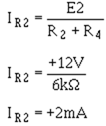
Next, compute the voltage drop across R2 (ER2):

Then, compute the voltage at point B:

Since point A and point B will be at the same potential in an operational amplifier:
![]()
Now compute the voltage developed by R1 (ER1):
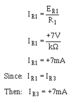
Compute the current through R1 (IR1):
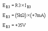
Compute the voltage developed by R3 (ER3):
Add this voltage to the voltage at point A to compute the output voltage (Eout):

This was the output desired, so the circuit works as a difference amplifier.
Q.28 What is the difference between a summing amplifier and an adder circuit?
Q.29 Can a summing amplifier have more than two inputs?
Q.30 What is a scaling amplifier?
Back
Home
Up
Next
Circuit for Q31 through Q33
Refer to figure 3-27 in answering Q31 through Q33.
Figure 3-27. – Circuit for Q31 through Q33.
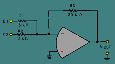
Q.31 What type of circuit is figure 3-27?
Q.32 If: E1 = +2VAnd: E2 = +6VThen Eout = ?
Q.33 What is the difference in potential between the inverting (-) and noninverting (+) inputs to the operational amplifier when:E1 = +6VandE2 = +2V
Q.34 What is the difference between a subtractor and a difference amplifier?
Q.35 Can a difference amplifier have more than two inputs?
Back
Home
Up
Next
Circuit for Q36 through Q38
Refer to figure 3-28 in answering Q36 through Q38.
Figure 3-28. – Circuit for Q36 through Q38.
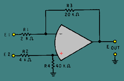
Q.36 What type of circuit is figure 3-28?
Q.37 If: E1 = +5VAnd: E2 = +11VThen Eout = ?
Q.38 What is the difference in potential between the inverting (-) and noninverting (+) inputs to the operational amplifier when:E1 = +2VandE2 = +4V
Back
Home
Up
Next
MAGNETIC AMPLIFIERS
You have now been shown various ways that electron tubes (NEETS, module 6) and transistors (NEETS, module 7) can be used to amplify signals. You have also been shown the way in which this is done. There is another type of amplifier in use – the MAGNETIC AMPLIFIER, sometimes called the MAG AMP.
The magnetic amplifier has certain advantages over other types of amplifiers. These include (1) high efficiency (up to 90 percent); (2) reliability (long life, freedom from maintenance, reduction of spare parts inventory); (3) ruggedness (shock and vibration resistance, high overload capability, freedom from effects of moisture); and (4) no warm-up time. The magnetic amplifier has no moving parts and can be hermetically sealed within a case similar to the conventional dry-type transformer.
However, the magnetic amplifier has a few disadvantages. For example, it cannot handle low-level signals; it is not useful at high frequencies; it has a time delay associated with the magnetic effects; and the output waveform is not an exact reproduction of the input waveform (poor fidelity).
The magnetic amplifier is important, however, to many phases of naval engineering because it provides a rugged, trouble-free device that has many applications aboard ship and in aircraft. These applications include throttle controls on the main engines of ships; speed, frequency, voltage, current, and temperature controls on auxiliary equipment; and fire control, servomechanisms, and stabilizers for guns, radar, and sonar equipment.
As stated earlier, the magnetic amplifier does not amplify magnetism, but uses electromagnetism to amplify a signal. It is a power amplifier with a very limited Frequency response. Technically, it falls into the classification of an audio amplifier; but, since the Frequency response is normally limited to 100 hertz and below, the magnetic amplifier is more correctly called a low-frequency amplifier.
The basic principle of a magnetic amplifier is very simple. (Remember, all amplifiers are current-control devices.) A magnetic amplifier uses a changing inductance to control the power delivered to a load.
BASIC OPERATION OF A MAGNETIC AMPLIFIER
Figure 3-29 shows a simple circuit with a variable inductor in series with a resistor (representing a load). The voltage source is 100 volts at 60 hertz.
Figure 3-29. – Variable inductor in series with a load.
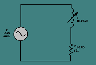
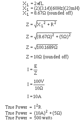
What happens when the inductance decreases? The end result is that the power in the load (true power) increases. Why? Look at the following formulas and see how each is affected by a decrease in inductance.
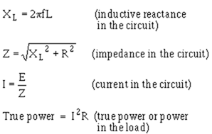
(True power is covered in NEETS, Module 2 – Introduction to Alternating Current and Transformers.)
As inductance (L) decreases, XL decreases. As XL decreases, Z decreases. As Z decreases, I increases. Finally, as I increases, true power increases.
This general conclusion can be confirmed by using some actual values of inductance in the formulas along with other values from figure 3-29.
If the value of inductance is 23 millihenries, the formulas yield the following values:
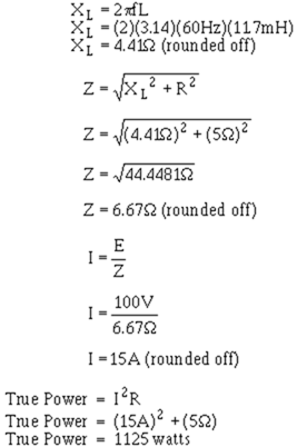
Now, if the value of inductance is decreased to 11.7 millihenries, the formulas yield the following values:
So a decrease in inductance of 11.3 millihenries (23 mH – 11.7 mH) causes an increase in power to the load (true power) of 625 watts (1125 W – 500 W). If it took 1 watt of power to change the inductance by 11.3 millihenries (by some electrical or mechanical means), figure 3-29 would represent a power amplifier with a gain of 625.
Q.39 What is the frequency classification of a magnetic amplifier?
Q.40 What is the basic principle of a magnetic amplifier?
Q.41 If inductance increases in a series LR circuit, what happens to true power?
Back
Home
Up
Next
METHODS OF CHANGING INDUCTANCE
Since changing the inductance of a coil enables the control of power to a load, what methods are available to change the inductance? Before answering that question, you should recall a few things about magnetism and inductors from NEETS, module 1 – Introduction to Matter, Energy, and Direct Current, chapter 1 – Matter, Energy, and Electricity; and module 2 – Introduction to Alternating Current and Transformers, chapter 2 – Inductance.
Permeability was defined as the measure of the ability of a material to act as a path for additional magnetic lines of force. Soft iron was presented as having high permeability compared with air. In fact, the permeability of unmagnetized iron is 5000 while air has a permeability of 1. A nonmagnetized piece of iron has high permeability because the tiny molecular magnets (Weber’s Theory) or the directions of electron spin (Domain Theory) are able to be aligned by a magnetic field. As they align, they act as a path for the magnetic lines of force.
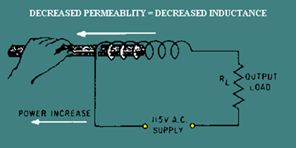
Earlier NEETS modules state that the inductance of a coil increases directly as the permeability of the core material increases. If a coil is wound around an iron core, the permeability of the core is 5000. Now, if the iron is pulled part way out of the coil of wire, the core is part iron and part air. The permeability of the core decreases. As the permeability of the core decreases, the inductance of the coil decreases. This increases the power delivered to the load (true power). This relationship is shown in figure 3-30.
The system shown in figure 3-30 is not too practical. Even if a motor were used in place of the hand that is shown, the resulting amplifier would be large, expensive, and not easily controlled. If the permeability of a core could be changed by electrical means rather than mechanical, a more practical system would result.
Figure 3-30. – Varying coil inductance with a movable coil.
High permeability depends on there being many molecular magnets (or electron spin directions) that can be aligned to provide a path for magnetic lines of force. If almost all of these available paths are already being used, the material is magnetized and there are no more paths for additional lines of force. The "flux density" (number of lines of force passing through a given area) is as high as it can be. This means that the permeability of the material has decreased. When this condition is reached, the core is said to be SATURATED because it is saturated (filled) with all the magnetic lines of force it can pass. At this point, the core has almost the same value of permeability as air (1) instead of the much higher value of permeability (5000) that it had when it was unmagnetized.
Of course, the permeability does not suddenly change from 5000 to 1. The permeability changes as the magnetizing force changes until saturation is reached. At saturation, permeability remains very low no matter how much the magnetizing force increases. If you were to draw a graph of the flux density compared to the magnetizing force, you would have something similar to the graph shown in figure 3-31. Figure 3-31 also includes a curve representing the value of permeability as the magnetizing force increases. Point "s" in figure 3-31 is the point of saturation. The flux density does not increase above point "s," and the permeability is at a steady, low value.
Figure 3-31. – Magnetization and permeability curves.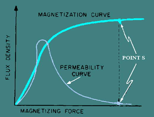
You have now seen how a change in the magnetizing force causes a change in permeability. The next question is, how do you change the magnetizing force? Magnetizing force is a function of AMPERE-TURNS. (An ampere-turn is the magnetomotive force developed by 1 ampere of current flowing in a coil of one turn.) If you increase the ampere-turns of a coil, the magnetizing force increases. Since it is not practical to increase the number of turns, the easiest way to accomplish this is to increase the current through the coil.
If you increase the current through a coil, you increase the ampere-turns. By increasing the ampere-turns you increase the magnetizing force. At some point, this causes a decrease in the permeability of the core. With the permeability of the core decreased, the inductance of the coil decreases. As said before, a decrease in the inductance causes an increase in power through the load. A device that uses this arrangement is called a SATURABLE-CORE REACTOR or SATURABLE REACTOR.
SATURABLE-CORE REACTOR
A saturable-core reactor is a magnetic-core reactor (coil) whose reactance is controlled by changing the permeability of the core. The permeability of the core is changed by varying a unidirectional flux (flux in one direction) through the core.
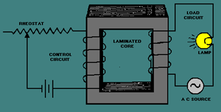
Figure 3-32 shows a saturable-core reactor that is used to control the intensity of a lamp. Notice that two coils are wound around a single core. The coil on the left is connected to a rheostat and a battery. This coil is called the control coil because it is part of the control circuit. The coil on the right is connected to a lamp (the load) and an a.c. source. This coil is called the load coil because it is part of the load circuit.
As the wiper (the movable connection) of the rheostat is moved toward the right, there is less resistance in the control circuit. With less resistance, the control-circuit current increases. This causes the amount of magnetism in the core to increase and the inductance of the coil in the load circuit to decrease (because the core is common to both coils). With less inductance in the load circuit, load current increases and the lamp gets brighter.
Figure 3-32. – A simple saturable-core reactor circuit.
The schematic diagram of this circuit is shown in figure 3-33. L1 is the schematic symbol for a saturable-core reactor. The control winding is shown with five loops, and the load winding is shown with three loops. The double bar between the inductors stands for an iron core, and the symbol that cuts across the two windings is a saturable-core symbol indicating that the two windings share a saturable core.
Figure 3-33. – Schematic diagram of a simple saturable-core reactor.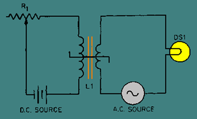
Now that you have seen the basic operation of a saturable-core reactor, there is one other idea to discuss before moving on to the circuitry of a magnetic amplifier. There is a point upon the magnetization curve where the saturable-core reactor should be operated. The ideal operating point is the place in which a small increase in control current will cause a large increase in output power and a small decrease in control current will cause a large decrease in output power. This point is on the flattest portion of the permeability curve (after its peak).
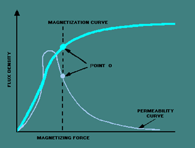
Figure 3-34 shows the magnetization and permeability curves for a saturable-core reactor with the ideal operating point (point "O") indicated. Notice point "O" on the magnetization curve. The portion of the magnetization curve where point "O" is located is called the KNEE OF THE CURVE. The knee of the curve is the point of maximum curvature. It is called the "knee" because it looks like the knee of a leg that is bent. Saturable-core reactors and magnetic amplifiers should be operated on the knee of the magnetization curve.
Figure 3-34. – Magnetization and permeability curves with operating point.
Back
Home
Up
Next
Flux paths in a saturable-core reactor. FLUX AIDING
When the saturable-core reactor is set at the knee of the magnetization curve, any small increase in control current will cause a large increase in load current. Any small decrease in control current will cause a large decrease in load current. That is why point "O" is the ideal operating point-because small changes in control current will cause large changes in load current. In other words, the saturable-core reactor can amplify the control current. However, a saturable-core reactor is NOT a magnetic amplifier. You will find out a little later how a magnetic amplifier differs from a saturable-core reactor. First you should know a few more things about the saturable-core reactor.
If a d.c. voltage is applied to the control winding of a saturable-core reactor and an a.c. voltage is applied to the load windings, the a.c. flux will aid the d.c. flux on one half cycle and oppose the d.c. flux on the other half cycle. This is shown in figure 3-35. Load flux is indicated by the dashed-line arrows, and control flux is indicated by the solid-line arrows. View (A) shows the load and control flux adding during one half cycle of the a.c. View (B) of the figure shows the load and control flux opposing during the other half cycle of the a.c.
Figure 3-35A. – Flux paths in a saturable-core reactor. FLUX AIDING
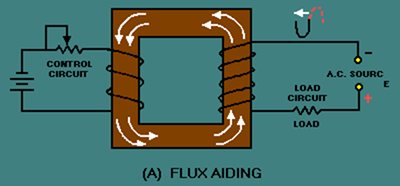
Figure 3-35B. – Flux paths in a saturable-core reactor. FLUX OPPOSING
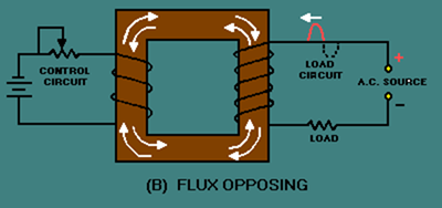
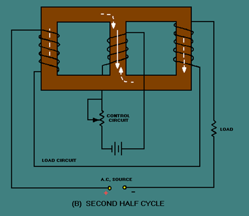
This situation causes the operating point of the saturable-core reactor to shift with the applied a.c. However, the situation would be better if the load flux was not an influence on the control flux. Figure 3-36 shows a circuit in which this is accomplished.
During the first half cycle, the load circuit flux (dashed-line arrows) cancels in the center leg of the core. This is shown in figure 3-36, view (A). As a result, there is no effect upon the flux from the control circuit. During the second half cycle, the polarity of the a.c. (and therefore the polarity of the flux) reverses as shown in view (B). The result is the same as it was during the first half cycle. There is no effect upon the control circuit flux.
Figure 3-36A. – Three-legged, saturable-core reactor. FIRST HALF CYCLE
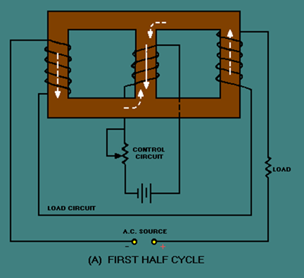
Figure 3-36B. – Three-legged, saturable-core reactor. SECOND HALF CYCLE
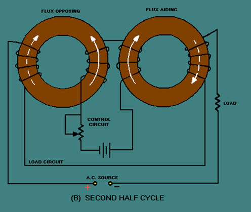
Another approach to solving the problem of load flux affecting control flux is shown in figure 3-37. Figure 3-37 shows a toroidal saturable-core reactor. The shape of these cores is a toroid (donut shape). The windings are wound around the cores so that the load flux aids the control flux in one core and opposes the control flux in the other core.
During the first half cycle, the flux aids in the left core and opposes in the right core, as shown in figure 3-37, view (A). During the second half cycle, the flux opposes in the left core and aids in the right core, as shown in view (B). Regardless of the amount of load flux or polarity of the load voltage, there is no net effect of load flux on control flux.
Figure 3-37A. – Toroidal saturable-core reactor. FIRST HALF CYCLE
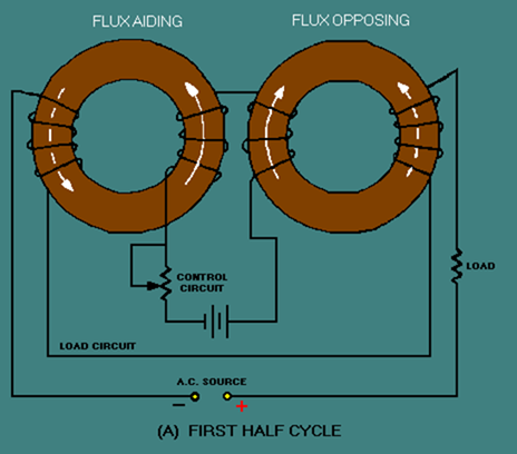
Figure 3-37B. – Toroidal saturable-core reactor. SECOND HALF CYCLE
Figures 3-36 and 3-37 both represent practical, workable saturable-core reactors. Circuits similar to these are actually used to control lighting in auditoriums or electric industrial furnaces. These circuits are sometimes referred to as magnetic amplifiers, but that is NOT technically correct. A magnetic amplifier differs from a saturable-core reactor in one important aspect: A magnetic amplifier has a rectifier in addition to a saturable-core reactor.
Q.42 If the permeability of the core of a coil increases, what happens to (a) inductance and (b) true power in the circuit?
Q.43 What happens to the permeability of an iron core as the current increases from the operating point to a large value?
Q.44 If two coils are wound on a single iron core, what will a change in current in one coil cause in the other coil?
Q.45 What symbol in figure 3-33 indicates a saturable core connecting two windings?
Back
Home
Up
Next


