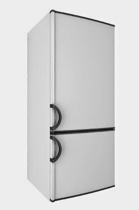
Fault finding guide for vapour compression systems
This checklist will assist in the quick diagnosis of faults on vapour compression systems.
Visual fault finding
Compressor not running
1 Main supply isolator open.
2 Fuse blown.
3 Overload open circuit.
4 Control circuit open (low pressure switch, high pressure switch or thermostat).
Fixture temperature too high
1 High evaporator load.
2 Defrost heater(s) energized.
3 Condenser blocked with dirt.
4 Restricted air flow over the condenser or restricted water flow.
5 Condenser fan inoperative.
6 Evaporator blocked with ice.
7 Evaporator fan inoperative.
8 Vapour bubbles in sight glass (possible shortage of refrigerant).
9 Frosting liquid line (blocked drier).
10 Broken or loose drive belts.
11 Expansion valve bulb loose on suction line or broken capillary.
System noisy
1 Evaporator/condenser fan blades touching fan guards or loose on the motor shaft.
2 Compressor oil sight glass empty (shortage of oil or oil entrainment).
3 Compressor head frosted (compressor pumping liquid refrigerant).
4 Loose motor pulley, compressor flywheel, compressor mountings.
Pressures
If the fault is not obvious after visual inspection:
1 Attach compound and pressure gauges.
2 Check that the compressor is pumping.
3 Observe operating pressures.
High discharge pressure
1 Overcharge of refrigerant.
2 Air in the system.
3 Dirty condenser, poor air supply.
4 Inadequate water flow.
5 High load imposed on the evaporator.
Low discharge pressure
1 Shortage of refrigerant.
2 Compressor inefficient.
High suction pressure
1 Compressor inefficient.
2 Overcharge of refrigerant (capillary systems only).
3 Expansion valve defective.
4 High evaporator load.
5 Defrost system operating when compressor is running.
Low suction pressure
1 Shortage of refrigerant.
2 Blocked or defective expansion valve.
3 Blockage in liquid line, drier solenoid valve or shut-off valve.
4 Blocked evaporator (excessive ice build-up).
5 Inoperative evaporator fan.
6 Defective water pump or blocked water filter on a chiller system.
Note: a temperature difference across any component in the liquid line is an indication of a partial restriction.
Advanced diagnosis
Expansion valve capacity too small
1 No subcooling of the refrigerant liquid.
2 The pressure drop across the expansion valve is less than that for which it was dimensioned.
3 Incorrect expansion valve bulb location (too cold or being cooled).
4 Large pressure drop across the evaporator.
5 Expansion valve blocked by ice or foreign objects.
6 Incorrect expansion valve external equalizer location.
Liquid knock in compressor during start-up
1 Compressor discharge valve letting by (refrigerant condenses in the discharge line to enter the compressor).
2 Low ambient temperature in condensing unit location (refrigerant condenses in the compressor).
When refrigerant vapour condenses in the discharge line, which is common in equipment located outside and during winter operation, or with low ambient temperature combined with long ‘off’ cycles, liquid refrigerant can enter the cylinders if discharge valves are not seating correctly. This condition can be attributed to poorly designed pipework (see ‘Pipework and oil traps’ in Chapter 10).
3 Suction line passing through low ambient temperature, or not insulated when installed in a low temperature coldroom (refrigerant condenses in suction line).
When condensation occurs in the suction line, refrigerant will be drawn into the cylinders when the compressor starts.
4 Suction line has a free fall to the compressor.
This result of poor pipework design can be overcome by installing an oil trap in the suction line.
5 Expansion valve bulb mounting gives poor thermal contact, or the bulb is located in a warm place.
The expansion valve thermal element will respond to temperature. If it is incorrectly located it can produce overfilling of the evaporator during operation, which may allow liquid refrigerant to enter the suction line and compressor. This is more likely to occur with short suction line runs.
Liquid knock in the compressor during operation
Evaporator pressure too low, or suction superheat too narrow Suction pressure too low, or suction superheat too wide
A low pressure reading on the compound gauge during operation does not necessarily indicate malfunction. The pressure reading must be related to the design temperature and the temperature difference recommended to the product being stored.
Single phase/three phase motor compressors and remote-drive motors
Compressor will not run
1 Fuse blown.
2 Main isolator open.
3 No supply at motor terminals.
4 Overload open circuit.
5 Control circuit open.
6 Burnt-out motor windings.
Compressor hums but does not start
1 Incorrect wiring to motor winding (3 ph).
2 Low line voltage.
3 Start capacitor open circuit.
4 Relay inoperative.
5 Motor winding open circuit.
6 Seized compressor.
7 Piston or impellor jammed by broken component.
Compressor does not attain design speed
1 Incorrectly wired motor winding (3 ph).
2 Low line voltage (3 ph).
3 Defective relay.
4 Start capacitor defective.
5 High discharge pressure.
6 Star/delta motor compressor not unloaded (3 ph).
Compressor short cycles
1 Control differential too narrow.
2 Valve plate letting by.
3 Motor overloading.
4 Shortage of refrigerant.
5 Expansion valve defective.
6 Restriction in system.
7 High pressure cut-out set too low (switch operating too soon).

