Internal Flows
The material in this chapter is focused on the influence of viscosity on the flows internal to boundaries, such as flow in a pipe or between rotating cylinders. The next chapter will focus on flows that are external to a boundary, such as an airfoil. The parameter that is of primary interest in an internal flow is the Reynolds number, Re = VL / n, where L is the primary characteristic length (e.g., the diameter of a pipe) in the problem of interest and V is usually the average velocity in a flow. We will consider internal flows in pipes, between parallel plates and rotating cylinders, and in open channels. If the Reynolds number is relatively low, the flow is laminar (see Sec. 3.2); if it is relatively high, it is turbulent. For pipe flows, the flow is assumed to be laminar if Re < 2000; for flow between wide parallel plates, it is laminar if Re < 1500; for flow between rotating concentric cylinders, it is laminar and flows in a circular motion below Re < 1700; and in the open channels of interest, it is assumed to be turbulent.
7.1 Entrance Flow
The flows mentioned above refer to developed flows, flows in which the velocity profiles do not change in the streamwise direction. In the region near a geometry
 Figure 7.1 The laminar-flow entrance region in a pipe or between parallel plates.
change, such as an elbow, a valve, or near an entrance, the velocity profile changes in the flow direction. Let’s consider the changes in the entrance region for a laminar flow in a pipe or between parallel plates. The entrance length L is shown in Fig. 7.1.
The velocity profile very near the entrance is essentially uniform, the viscous wall layer grows until it permeates the entire cross section over the inviscid core length L ; the profile continues to develop into a developed flow at the end of the profile development region.
For a laminar flow in a pipe, with a uniform velocity profile at the entrance,
where V is the average velocity and D is the diameter. The inviscid core is about half of the entrance length.1 It should be mentioned that laminar flows in pipes have been observed at Reynolds numbers as high as 40 000 in extremely controlled flows in smooth pipes in a building free of vibrations; for a conventional pipe with a rough wall we use 2000 as the limit2 for a laminar flow.
For flow between wide parallel plates, with a uniform profile at the entrance,
where h is the distance between the plates and V is the average velocity. A laminar flow cannot exist for Re > 7700; a value of 1500 is used as the limit for flow in a conventional channel.
The entrance region for a developed turbulent flow is displayed in Fig. 7.2. The velocity profile is developed at the length L but the characteristics of the turbulence
Figure 7.2 The turbulent-flow entrance region in a pipe.
in the flow require the additional length. For large Reynolds numbers exceeding 105 in a pipe, we use
For a flow with Re = 4000 the lengths are possibly five times those listed in Eq. (7.3),
due to the initial laminar development followed by the development of turbulence.
(Detailed results have not been reported for flows in which Re < 105.)
The pressure variation is shown in Fig. 7.3. The initial transition to turbulence from the wall of the pipe is noted in the figure. The pressure variation for the laminar
 Figure 7.3 Pressure variation in a pipe for both laminar and turbulent flows.
flow is higher in the entrance region than in the fully-developed region due to the larger wall shear and the increasing momentum flux.
7.2 Laminar Flow in a Pipe
Steady, developed laminar flow in a pipe will be derived applying Newton’s second law to the element of Fig. 7.4 or using the appropriate Navier-Stokes equation of Chap. 5. Either derivation can be used.
THE ELEMENTAL APPROACH
The element of fluid shown in Fig.7.4 can be considered a control volume into and from which the fluid flows or it can be considered a mass of fluid at a particular moment. Considering it to be an instantaneous mass of fluid that is not accelerating in this steady, developed flow, Newton’s second law takes the form
where τ is the shear on the wall of the element and γ is the specific weight of the fluid. This simplifies to
Figure 7.4 Steady, developed flow in a pipe.
using dh = − sinθdx with h measured in the vertical direction. Note that this equation can be applied to either a laminar or a turbulent flow. For a laminar flow, the shear stress t is related to the velocity gradient3 by Eq. (1.13):
Because we assume a developed flow (no change of the velocity profile in the flow direction), the left-hand side of the equation is a function of r only, so d /dx( p + γ h) must be at most a constant (it cannot depend on r since there is no radial acceleration; we assume the pipe is relatively small, so there is no variation of pressure with r). Hence, we can write
The above velocity profile is a parabolic profile; the flow is sometimes referred to as a Poiseuille flow.
The same result can be obtained by solving the appropriate Navier-Stokes equation. If that is not of interest, skip the next part.
APPLYING THE NAVIER-STOKES EQUATIONS
The z-component differential momentum equation using cylindrical coordinates from Table 5.1 is applied to a steady, developed flow in a circular pipe. For the present
situation we wish to refer to the coordinate in the flow direction as x and the velocity component in the x-direction as u(x); so, let’s replace the z with x and the vz with u. Then the differential equation takes the form
Observe that the left-hand side of the equation is zero, i.e., the fluid particles are not
accelerating. Using ρg x= γ sinθ = −γ dh/dx, the above equation simplifies to
Now, we see that the left-hand side of Eq. (7.11) is at most a function of x, and the right-hand side is a function of r. This means that each side is at most a constant, say l, since x and r can be varied independently of each other. So, we replace the partial derivatives with ordinary derivatives and write Eq. (7.11) as
Refer to Fig. 7.4: the two boundary conditions are, u is finite at r = 0, and u = 0 at r = r . Thus, A = 0 and B = −λr 2 /4. Since l is the left-hand side of Eq. (7.11), we can write Eq. (7.15) as
This is the prabolic velocity distribution of a developed laminar flow in a pipe, sometimes called a Poiseuille flow. For a horizontal pipe, dh/dx = 0 and
The first quantity of interest in the flow in a pipe is the average velocity V. If we express the constant-pressure gradient as dp/dx = Δp/L where Δp is the pressure
drop (a positive number) over the length L, there results
 The shear stress at the wall can be found by considering a control volume of length L in the pipe. For a horizontal pipe the pressure force balances the shear force so that the control volume yields
![]() Sometimes a dimensionless wall shear called the friction factor f is used. It is defined to be
Sometimes a dimensionless wall shear called the friction factor f is used. It is defined to be
 We also refer to a head loss h1 ρV 2defined as Δ p/γ . By combining the above equations,
it can be expressed as the Darcy-Weisbach equation:
It is valid for both a laminar and a turbulent flow in a pipe. In terms of the Reynolds number, the friction factor for a laminar flow is [combining Eqs. (7.20) and (7.23)]
 where Re = VD/n. If this is substituted into Eq. (7.23), we see that the head loss is directly proportional to the average velocity in a laminar flow, which is also true of a laminar flow in a conduit of any cross section.
EXAMPLE 7.1
The pressure drop over a 30-m length of 1-cm-diameter horizontal pipe trans- porting water at 20°C is measured to be 2 kPa. A laminar flow is assumed. Determine (a) the maximum velocity in the pipe, (b) the Reynolds number, (c) the wall shear stress, and (d) the friction factor.
Solution
(a) The maximum velocity is found to be
Note: The pressure must be in pascals in order for the units to check. It is wise to make sure the units check when equations are used for the first time. The above units are checked as follows:
(b) The Reynolds number, a dimensionless quantity, is (use V = umax / 2)
This exceeds 2000 but a laminar flow can exist at higher Reynolds numbers if a smooth pipe is used and care is taken to provide a flow free of disturbances. Note how low the velocity is in this relatively small pipe. Laminar flows do not exist in most engineering applications unless the fluid is extremely viscous or the dimensions are quite small.
(c) The wall shear stress due to the viscous effects is found to be
If we had used the pressure in kPa, the stress would have had units of kPa.
(d) Finally, the friction factor, a dimensionless quantity, is
7.3 Laminar Flow Between Parallel Plates
Steady, developed laminar flow between parallel plates (the top plate moving with velocity U) will be derived applying Newton’s second law to the element of Fig. 7.5 or using the appropriate Navier-Stokes equation of Chap. 5. Either derivation can be used.
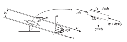 Figure 7.5 Steady, developed flow between parallel plates.
THE ELEMENTAL APPROACH
The element of fluid shown in Fig. 7.5 can be considered a control volume into and from which the fluid flows or it can be considered a mass of fluid at a particular moment. Considering it to be an instantaneous mass of fluid that is not accelerating in this steady, developed flow, Newton’s second law takes the form
where t is the shear on the wall of the element and g is the specific weight of the fluid. We have assumed a unit length into the paper (in the z-direction). To simplify, divide by dxdy and use dh = − sinθ dx with h measured in the vertical direction:
![]() For this laminar flow the shear stress is related to the velocity gradient by τ = μdu/dy so that Eq. (7.26) becomes
For this laminar flow the shear stress is related to the velocity gradient by τ = μdu/dy so that Eq. (7.26) becomes
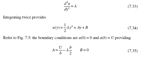
The left-hand side of the equation is a function of y only for this developed flow (we assume a wide channel with an aspect ratio in excess of 8) and the right-hand side is a function of x only. So, we can integrate twice on y to obtain
Using the boundary conditions u(0) = 0 and u(b) = U, the constants of integration are evaluated and a parabolic profile results:
 If the plates are horizontal and U = 0, the velocity profile simplifies to
 where we have let d(p + g h)/dx = −Δp/L for the horizontal plates, where Δ p is the pressure drop, a positive quantity.
If the flow is due only to the top horizontal plate moving with velocity U, with zero pressure gradient, it is a Couette flow so that u(y) = Uy/b. If both plates are stationary and the flow is due only to a pressure gradient, it is a Poiseuille flow. The same result can be obtained by solving the appropriate Navier-Stokes equa- tion. If that is not of interest, skip the next part.
APPLYING THE NAVIER-STOKES EQUATIONS
The x-component differential momentum equation in rectangular coordinates [see Eq. (5.18)] is selected for this steady, developed flow with streamlines parallel to the walls in a wide channel (at least an 8 to 1 aspect ratio):
 where the channel makes an angle of q with the horizontal. Using dh = −dx sinq this partial differential equation simplifies to
where the partial derivatives have been replaced by ordinary derivatives since u depends on y only and p is a function of x only.
Because the left-hand side of Eq. (7.32) is a function of y and the right-hand side is a function of x, both of which can be varied independent of each other, the two sides can be at most a constant, say l, so that
where l has been used as the right-hand side of Eq. (7.32).
In a horizontal channel we can write d(p + lh)/dx = −Δp/L. If U = 0 the velocity profile is
This is a Poiseuille flow. If the pressure gradient is zero and the motion of the top plate causes the flow, it is called a Couette flow with u(y) = Uy/b.
QUANTITIES OF INTEREST
Let us consider several quantities of interest for the case of two fixed plates with U = 0. The first quantity of interest in the flow is the average velocity V. The average velocity is, assuming unit width of the plates
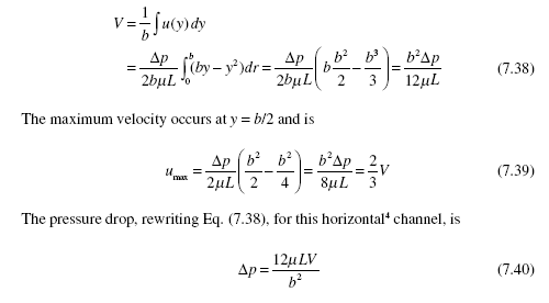 The shear stress at either wall can be found by considering a free body of length L
in the channel. For a horizontal channel the pressure force balances the shear force:
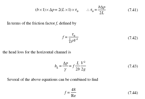 where Re = bV/n. If this is substituted into Eq. (7.43), we see that the head loss is directly proportional to the average velocity in a laminar flow.
The above equations were derived for a channel with an aspect ratio greater than 8. For lower aspect-ratio channels, the sides would require additional terms since the shear acting on the side walls would influence the central part of the flow.
If interest is in a horizontal channel flow where the top plate is moving and there is no pressure gradient, the velocity profile would be the linear profile
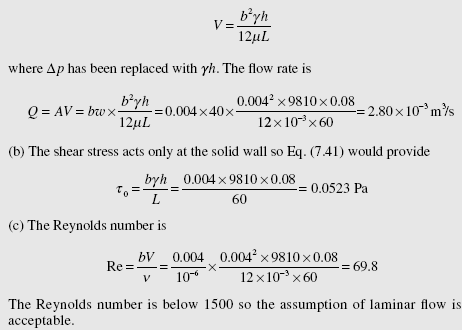
The thin layer of rain at 20°C flows down a parking lot at a relatively constant depth of 4 mm. The area is 40 m wide with a slope of 8 cm over 60 m of length. Estimate (a) the flow rate, (b) shear at the surface, and (c) the Reynolds number.
(a) The velocity profile can be assumed to be one half of the profile shown in Fig. 7.5, assuming a laminar flow. The average velocity would remain as given by Eq. (7.38), i.e.,


