3.1 Classification of Fluid Flows
Fluid mechanics is a subject in which many rather complicated phenomena are encountered, so it is important that we understand some of the descriptions and
simplifications of several special fluid flows. Such special flows will be studied in detail in later chapters. Here we will attempt to classify them in as much detail as possible.
UNIFORM, ONE-, TWO-, AND THREE-DIMENSIONAL FLOWS
A dependent variable in our study of fluids depends, in general, on the three space coordinates and time, i.e., V(x, y, z, t). The flow that depends on three space coordinates is a three-dimensional flow; it could be a steady flow if time is not involved, such as would be the case in the flow near the intersection of a wing and the fuselage of an aircraft flying at a constant speed. The flow in a washing machine would be an unsteady, three-dimensional flow.
Certain flows can be approximated as two-dimensional flows; flows over a wide weir, in the entrance region of a pipe, and around a sphere are examples that are of special interest. In such two-dimensional flows the dependent variables depend on only two space variables, i.e., p(r,q) or V(x, y, t). If the space coordinates are x and y, we refer to the flow as a plane flow.
One-dimensional flows are flows in which the velocity depends on only one space variable. They are of special interest in our introductory study since they include the flows in pipes and channels, the two most studied flows in an introductory course. For flow in a long pipe, the velocity depends on the radius r, and in a wide channel (parallel plates) it depends on y, as shown in Fig. 3.4.
The flows shown in Fig. 3.4 are also referred to as developed flows; the velocity profiles do not change with respect to the downstream coordinate. This demands that the pipe flow shown is many diameters downstream of any change in geometry, such as an entrance, a valve, an elbow, or a contraction or expansion. If the flow has not developed, the velocity field depends on more than one space coordinate, as is the case near a geometry change. The developed flow may be unsteady, i.e., it may depend on time, such as when a valve is being opened or closed.
Finally, there is the uniform flow, as shown in Fig. 3.5; the velocity profile, and other properties such as pressure, is uniform across the section of pipe. This profile
 Figure 3.4 One-dimensional flow: (a) flow in a pipe and (b) flow in a wide channel.
Figure 3.5 A uniform flow in a pipe.
is often assumed in pipe and channel flow problems since it approximates the more common turbulent flow so well. We will make this assumption in many of the problems throughout this book.
VISCOUS AND INVISCID FLOWS
In an inviscid flow the effects of viscosity can be completely neglected with no significant effects on the solution to a problem. All fluids have viscosity and if the viscous effects cannot be neglected, it is a viscous flow. Viscous effects are very important in pipe flows and many other kinds of flows inside conduits; they lead to losses and require pumps in long pipelines. But, there are flows in which we can neglect the influence of viscosity. Consider an external flow, flow external to a body, such as the flow around an airfoil or a hydrofoil, as shown in Fig. 3.6. If the airfoil is moving relatively fast (faster than about 1 m/s), the flow away from a thin layer near the boundary, a boundary layer, can be assumed to have zero viscosity with no significant effect on the solution to the flow field (the velocity, pressure, temperature fields). All the viscous effects are concentrated inside the boundary layer and cause the velocity to be zero at the surface of the airfoil, the no-slip condition. Since inviscid flows are easier to solve than viscous flows, the recognition that the viscosity can be ignored in the flow away from the surface leads to much simpler solutions. This will be demonstrated in Chap. 8 (External Flows).
Figure 3.6 Flow around an airfoil.
LAMINAR AND TURBULENT FLOWS
A viscous flow is either a laminar flow or a turbulent flow. In a turbulent flow there is mixing of fluid particles so that the motion of a given particle is random and very irregular; statistical averages are used to specify the velocity, the pressure, and other quantities of interest. Such an average may be “steady” in that it is independent of time, or the average may be unsteady and depend on time. Figure 3.7 shows steady and unsteady turbulent flows. Notice the noisy turbulent flow from a faucet when you get a drink of water.
In a laminar flow there is negligible mixing of fluid particles; the motion is smooth and noiseless, like the slow flow of water from a faucet. If a dye is injected into a laminar flow, it remains distinct for a relatively long period of time. The dye would be immediately diffused if the flow were turbulent. Figure 3.8 shows a steady and an unsteady laminar flow. A laminar flow could be made to appear turbulent by randomly controlling a valve in the flow of honey in a pipe so as to make the velocity appear as in Fig. 3.7. Yet, it would be a laminar flow since there would be no mixing of fluid particles. So, a simple display of V(t) is not sufficient to decide if a particular flow is laminar or turbulent. To be turbulent, the motion has to be random, as in Fig. 3.7, but it also has to have mixing of fluid particles.
As a flow starts from rest, as in a pipe when a valve is slightly opened, the flow starts out laminar, but as the average velocity increases, the laminar flow becomes unstable and turbulent flow ensues. In some cases, as in the flow between rotating cylinders, the unstable laminar flow develops into a secondary laminar flow of vortices, and then a third laminar flow, and finally a turbulent flow at higher speeds.
There is a quantity, called the Reynolds number, that is used to determine if a flow is laminar or turbulent. It is
where V is a characteristic velocity (the average velocity in a pipe or the speed of an airfoil), L is a characteristic length (the diameter of a pipe or the distance from the leading edge of a flat plate), and n is the kinematic viscosity. If the Reynolds number is larger than a critical Reynolds number, the flow is turbulent; if it is lower than a critical Reynolds number, the flow is laminar. For flow in a pipe, assuming the typically rough pipe wall, the critical Reynolds number is usually taken to be 2000; if the wall is smooth and free of vibrations, and the entering flow is free of disturbances, the critical Reynolds number can be as high as 40 000. The critical Reynolds number is different for each geometry. For flow between parallel plates, it is taken as 1500 using the average velocity and the distance between the plates. For a boundary layer on a flat plate, it is between 3 × 10⁵ and 106, using L as the distance from the leading edge.
We do not refer to an inviscid flow as laminar or turbulent. In an external flow, the inviscid flow is called a free-stream flow. A free stream has disturbances but the disturbances are not accompanied by shear stresses, another requirement of both laminar and turbulent flows. The free stream can also be irrotational or it can possess vorticity.
A boundary layer is a thin layer of fluid that develops on a body due to the viscosity causing the fluid to stick to the boundary; it causes the velocity to be zero at the wall. The viscous effects in such a layer can actually incinerate a satellite on reentry. Figure 3.9 shows the typical boundary layer on a flat plate. It is laminar near the leading edge and undergoes transition to a turbulent flow with sufficient
Figure 3.9 Boundary-layer flow on a flat plate.
length. For a smooth rigid plate with low free-stream fluctuation level, a laminar layer can exist up to Re = 106, L being the length along the plate; for a rough plate, or a vibrating plate, or high free-stream fluctuations, a laminar flow exists up to about Re = 3 × 10⁵.
INCOMPRESSIBLE AND COMPRESSIBLE FLOWS
Liquid flows are assumed to be incompressible in most situations (water hammer1 is an exception). In such incompressible flows the density of a fluid particle as it moves along is assumed to be constant, i.e.,
![]() This does not demand that the density of all the fluid particles be the same. For example, salt could be added to a water flow at some point in a pipe so that down- stream of the point the density would be greater than at some upstream point. Atmo spheric air at low speeds is incompressible but the density decreases with increased elevation, i.e., r = r(z), where z is vertical. We usually assume a fluid to have constant density when we make the assumption of incompressibility. Constant density requires
This does not demand that the density of all the fluid particles be the same. For example, salt could be added to a water flow at some point in a pipe so that down- stream of the point the density would be greater than at some upstream point. Atmo spheric air at low speeds is incompressible but the density decreases with increased elevation, i.e., r = r(z), where z is vertical. We usually assume a fluid to have constant density when we make the assumption of incompressibility. Constant density requires
![]() The flow of air can be assumed to be incompressible if the velocity is sufficiently low. Air flow in conduits, around automobiles and small aircraft, and the takeoff and landing of commercial aircraft are all examples of incompressible airflows. The Mach number M where
The flow of air can be assumed to be incompressible if the velocity is sufficiently low. Air flow in conduits, around automobiles and small aircraft, and the takeoff and landing of commercial aircraft are all examples of incompressible airflows. The Mach number M where
is used to determine if a flow is compressible; V is the characteristic velocity and ![]() c
c
is the speed of sound. If M < 0.3, we assume the flow to be incompressible. For air near sea level this is about 100 m/s (200 mph) so many air flows can be assumed to be incompressible. Compressibility effects are considered in some detail in Chap. 9 (Compressible Flows).
EXAMPLE 3.3
A river flowing through campus appears quite placid. A leaf floats by and we estimate that it floats about 2 m in 10 s. We wade in the water and estimate the depth to be about 60 cm. Is the flow laminar or turbulent?
Solution
We estimate the Reynolds number to be, assuming T = 20°C and using Table C.1,
The flow is highly turbulent at this Reynolds number, contrary to our observation of the placid flow. Most internal flows are turbulent, as observed when we drink from a drinking fountain. Laminar flows are of minimal importance to engineers when compared to turbulent flows; a lubrication problem is one exception.
3.2 Bernoulli’s Equation
Bernoulli’s equation may be the most often used equation from fluid mechanics, but it is also the most often misused equation. In this section it will be derived and the restrictions required for its derivation will be highlighted. But, before the equation is derived, consider the five assumptions required: negligible viscous effects (no shear stresses), constant density, steady flow, the flow is along a streamline, and the velocity is measured in an inertial reference frame.
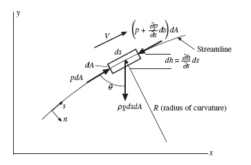
We apply Newton’s second law to a cylindrical particle that is moving on a streamline, as shown in Fig. 3.10. A summation of infinitesimal forces acting on the particle is
![]() where a is the s-component of the acceleration vector. It is given by Eq. (3.9)
where a is the s-component of the acceleration vector. It is given by Eq. (3.9)
where we think of the x-direction being in the s-direction so that u = V:
where ∂ V/∂ t = 0, assuming a steady flow. (This leads to the same acceleration expression as presented in physics or dynamics where ax = VdV/dx, providing an
Figure 3.10 A particle moving along a streamline.
inertial reference frame is used in which no Coriolis or other acceleration components are present.) Next, we observe that
 Now, divide Eq. (3.19) by dsdA and use the above expressions for as and cosq and earrange. There results
![]() If we assume that the density r is constant (this is more restrictive than incompressibility) so it can be moved after the partial derivative, and we recognize that V∂ V/∂ s = ∂ (V 2/2)/∂ s, we can write our equation as
If we assume that the density r is constant (this is more restrictive than incompressibility) so it can be moved after the partial derivative, and we recognize that V∂ V/∂ s = ∂ (V 2/2)/∂ s, we can write our equation as
This means that along a streamline the quantity in parentheses is constant, i.e.,
where the constant may change from one streamline to the next; along a given streamline the sum of the three terms is constant. This is often written, referring to two points on the same streamline, as
Either of the two forms above is the famous Bernoulli’s equation. Let’s once again state the assumptions required to use Bernoulli’s equation:
• Inviscid flow (no shear stresses)
• Constant density
• Steady flow
• Along a streamline
• Applied in an inertial reference frame
The first three listed are primarily ones usually considered. There are special applications where the last two must be taken into account; but those special applications will not be presented in this book. Also, we often refer to a constant-density flow as an incompressible flow, even though constant density is more restrictive [refer to the comments after Eq. (3.16)]. This is because incompressible flows, in which the density changes from one streamline to the next, such as in atmospheric flows, are not encountered in an introductory course.
Note that the units on all the terms in Eq. (3.26) are meters. Consequently, V 2/2g is called the velocity head, p/rg is the pressure head, and h is simply the head. The sum of the three terms is often referred to as the total head. The pressure p is the static pressure and the sum p + rV 2/2 is the total pressure or stagnation pressure since it is the pressure at a stagnation point, a point where the fluid is brought to rest along a streamline.
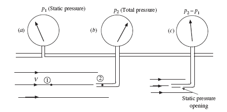
The difference in the pressures can be observed by considering the measuring probes shown in Fig. 3.11. The probe in Fig. 3.11a is a piezometer; it measures the
Figure 3.11 Pressure probes: (a) the piezometer, (b) a pitot tube, and (c) a pitot-static tube.
static pressure, or simply, the pressure at point 1. The pitot tube in Fig. 3.11b measures the total pressure, the pressure at a point where the velocity is zero, as at point 2. And, the pitot-static tube, which has a small opening the side of the probe as shown in Fig. 3.11c, is used to measure the difference between the total pressure and the static pressure, i.e., rV 2/2; this is used to calculate the velocity. The expression for velocity is
 where point 2 must be a stagnation point with V2 = 0. So, if only the velocity is desired, we simply use the pitot-static probe shown in Fig. 3.11c.
Bernoulli’s equation is used in numerous fluid flows. It can be used in an internal flow over short reaches if the viscous effects can be neglected; such is the case in the well-rounded entrance to a pipe (see Fig. 3.12) or in a rather sudden contraction of a pipe. The velocity for such an entrance is approximated by Bernoulli’s equation to be
Another common application of the Bernoulli’s equation is from the free stream to the front area of a round object such as a sphere or a cylinder or an airfoil. A sketch
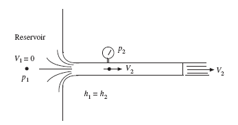 Figure 3.12 Flow from a reservoir through a pipe.
is helpful, as shown in Fig. 3.13. For many flow situations the flow separates from the surface, resulting in a separated flow, as shown. If the flow approaching the object is uniform, the constant in Eq. (3.25) will be the same for all the streamlines. Bernoulli’s equation can then be applied from the free stream to the stagnation point at the front of the object, and to points along the surface of the object up to the separation region.
We often solve problems involving a pipe exiting to the atmosphere. For such a situation the pressure just inside the pipe exit is the same as the atmospheric pressure just outside the pipe exit, since the streamlines exiting the pipe are straight near the exit (see Fig. 3.12). This is quite different from the entrance flow of Fig. 3.12 where the streamlines near the entrance are extremely curved.
To approximate the pressure variation normal to a curved streamline, consider the particle of Fig. 3.10 to be a parallelepiped with thickness dn normal to the
![]() streamline, with area dAs of the side, and with length ds. Use
streamline, with area dAs of the side, and with length ds. Use ![]()
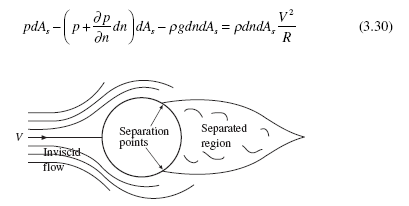 Figure 3.13 Flow around a sphere or a long cylinder.
where we have used the acceleration to be V 2/R, R being the radius of curvature in the assumed plane flow. If we assume that the effect of gravity is small compared to the acceleration term, this equation simplifies to
 Since we will use this equation to make estimations of pressure changes normal to
a streamline, we approximate ∂p/∂n = Δp/Δn and arrive at the relationship
Hence, we see that the pressure decreases as we move toward the center of the curved streamlines; this is experienced in a tornado where the pressure can be extremely low in the tornado’s “eye.” This reduced pressure is also used to measure the intensity of a hurricane; that is, lower the pressure in the hurricane’s center, larger the velocity at its outer edges.
EXAMPLE 3.4
The wind in a hurricane reaches 200 km/h. Estimate the force of the wind on a window facing the wind in a high-rise building if the window measures 1 m by 2 m. Use the density of the air to be 1.2 kg/m3.
Solution
Use Bernoulli’s equation to estimate the pressure on the window:
where the velocity must have units of m/s. To check the units, use kg = N · s2/m. Assume the pressure to be essentially constant over the window so that the force is then
This force is large enough to break many windows, especially if they are not properly designed.
EXAMPLE 3.5
A piezometer is used to measure the pressure in a pipe to be 20 cm of water. A pitot tube measures the total pressure to be 33 cm of water at the same general location. Estimate the velocity of the water in the pipe.
Solution
The velocity is found using Eq. (3.27):
 where we used the pressure relationship p = ρgh.
Quiz No. 1
1. A velocity field in a plane flow is given by V = 2yti + xj m/s. The magnitude of the acceleration at the point (4, 2 m) at t = 3 s is
(A) 52.5 m/s2
(B) 48.5 m/s2
(C) 30.5 m/s2
(D) 24.5 m/s2
2. A velocity field in a plane flow is given by V = 2xyi + ytj m/s. The vorticity of the fluid at the point (0, 4 m) at t = 3 s is
(A) −4k rad/s
(B) −3j rad/s
(C) −2k rad/s
(D) −3i rad/s
3. The parabolic velocity distribution in a channel flow is given by u(y) = 0.2(1 − y2) m/s, with y measured in centimeters. What is the acceleration of a fluid particle at a location where y = 0.5 cm?
(A) 0
(B) 2 m/s2
(C) 4 m/s2
(D) 5 m/s2
4. The equation of the streamline that passes through the point (2, −1) if the velocity field is given by V = 2xyi + y2 j m/s is
(A) x2 = 4y2
(B) x = −2y
(C) x2 = −4y
(D) x = 2y2
5. A drinking fountain has a 2-mm-diameter outlet. If the water is to be laminar, what is the maximum speed that the water should have?
(A) 0.5 m/s
(B) 1 m/s
(C) 2 m/s
(D) 4 m/s
6. Which of the following flows could be modeled as inviscid flows?
(a) Developed flow in a pipe
(b) Flow of water over a long weir
(c) Flow in a long, straight canal
(d) The flow of exhaust gases exiting a rocket
(e) Flow of blood in an artery
(f) Flow of air around a bullet
(g) Flow of air in a tornado
(A) d, e
(B) d, g
(C) b, e
(D) b, g
7. Salt is being added to fresh water in a pipe at a certain location. In the vicinity of that location the term Dr/Dt is nonzero. Which term in the expression for Dr/Dt is nonzero if the x-axis is along the pipe axis? Assume uniform conditions.
(A) u∂ρ /∂ y
(B) ρ∂u /∂ x
(C) u∂ρ /∂ x
(D) ρ∂u /∂ y
8. A pitot probe measures 10 cm of water on a small airplane flying where the temperature is 20°C. The speed of the airplane is nearest
(A) 40 m/s
(B) 50 m/s
(C) 60 m/s
(D) 70 m/s
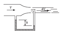
9. The fluid in the pipe is water and h = 10 cm of mercury. The velocity V is nearest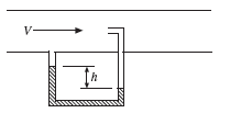
(A) 7 m/s
(B) 8 m/s
(C) 5 m/s
(D) 4 m/s
10. Select the false statement for Bernoulli’s equation
(A) It can be applied to an inertial coordinate system.
(B) It can be applied to an unsteady flow.
(C) It can be applied in an inviscid flow.
(D) It can be applied between two points along a streamline.
11. Water flows through a long-sweep elbow on a 2-cm-diameter pipe at an average velocity of 20 m/s. Estimate the increase in pressure from the inside of the pipe to the outside of the pipe midway through the elbow if the radius of curvature of the elbow averages 12 cm at the midway section.
(A) 60 kPa
(B) 66.7 kPa
(C) 75 kPa
(D) 90 kPa
Quiz No. 2
1. Find the rate of change of the density in a stratified flow where
r = 1000(1− 0.2z) and the velocity is V = 10(z – z2)i.
2. A velocity field is given in cylindrical coordinates as
What are the three acceleration components at the point (3 m, 90°)?
3. The traffic in a large city is to be studied. Explain how it would be done using (a) the Lagrangian approach and (b) the Eulerian approach.
4. Find the unit vector normal to the streamline at the point (2, 1) when t = 2 s if the velocity field is given by V = 2xyi + y2tj m/s.
5. A leaf is floating in a river seemingly quite slowly. It is timed to move 6 m in 40 s. If the river is about 1.2 m deep, determine if the placidly flowing river is laminar or turbulent.
6. Which of the following flows would definitely be modeled as a turbulent flow?
(a) Developed flow in a pipe
(b) Flow of water over a long weir
(c) Flow in a long, straight canal
(d) The flow of exhaust gases exiting a rocket
(e) Flow of blood in an artery
(f) Flow of air around a bullet
(g) Flow of air in a tornado
7. Air flows over and parallel to a 10-m-long flat plate at 2 m/s. How long is the laminar portion of the boundary layer if the air temperature is 30°C. Assume a high-fluctuation level on a smooth rigid plate.
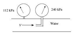
8. The pitot and piezometer probes read the total and static pressures as shown. Calculate the velocity V.
9. Determine the velocity V in the pipe if water is flowing and h = 20 cm of mercury.
10. A car is travelling at 120 km/h. Approximate the force of the air on the 20-cm-diameter flat lens on the headlight.


