Light
In This Chapter:
✔ Electromagnetic Waves
✔ Luminous Intensity and Flux
✔ Illumination
✔ Reflection of Light
✔ Refraction of Light
✔ Total Internal Reflection
✔ Apparent Depth
Electromagnetic Waves
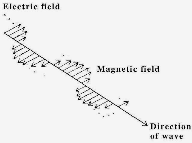
Electromagnetic waves consist of coupled electric and magnetic fields that vary periodically as they move through space. The electric and magnetic fields are perpendicular to each other and to the direction in which the waves travel (Figure 17-1), so the waves are transverse, and the variations in E and B occur simultaneously. Electromagnetic waves transport energy and require no material medium for their passage. Radio waves, light waves, X-rays, and gamma rays are examples of electromagnetic waves, and they differ only in frequency.
Figure 17-1
Note!
The color sensation produced by light waves de- pends on their frequency, with red light having the lowest visible frequencies and violet light the high- est. White light contains light waves of all visible frequencies.
Electromagnetic waves are generated by accelerated electric charges, usually electrons. Electrons oscillating back and forth in an antenna give off radio waves, for instance, and accelerated electrons in atoms give off light waves.
In free space, all electromagnetic waves have the velocity of light which is
Velocity of light = c = 3.00 × 10⁸ m/s = 186,000 mi/s
Luminous Intensity and Flux
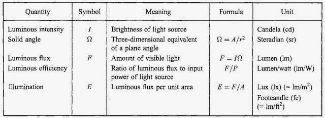
The brightness of a light source is called its luminous intensity I, whose unit is the candela (cd).The intensity of a light source is sometimes referred to as its candlepower.
The amount of visible light that falls on a given surface is called luminous flux F, whose unit is the lumen (lm). One lumen is equal to the luminous flux which falls on each 1 m2 of a sphere 1 m in radius when a 1-cd isotropic light source (one that radiates equally in all directions) is at the center of the sphere. Since the surface area of a sphere of radius r is 4pr2, a sphere whose radius is 1 m has 4p m2 of area, and the total luminous flux emitted by a 1-cd source is therefore 4p lm. Thus the luminous flux emitted by an isotropic light source of intensity I is given by
F = 4πI
Luminous flux= (4π)(luminous intensity)
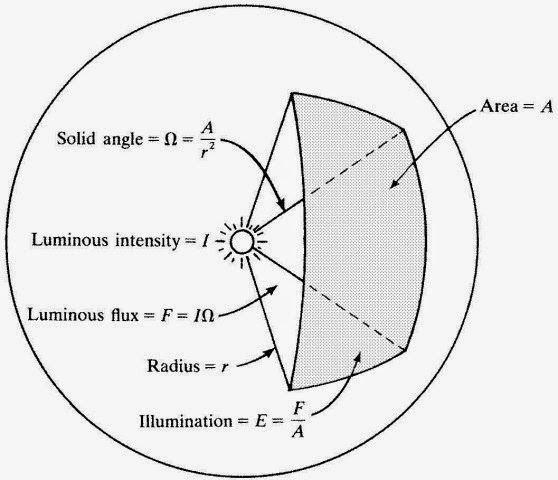
The above formula does not apply to a light source that radiates different fluxes in different directions. In such a situation, the concept of sol- id angle is needed. A solid angle is the counterpart in three dimensions of an ordinary angle in two dimensions. The solid angle W (Greek capital letter omega) subtended by area A on the surface of a sphere of radius r is given by
Ω = A/r2
Solid angle =areaonsurfaceofsphere/ (radius of sphere)2
The unit of solid angle is the steradian (sr); see Figure 17-2. Like the de- gree and the radian, the steradian is a dimensionless ratio that disappears in calculations.
The general definition of luminous flux is
F = IΩ
Luminous flux= (luminous intensity)(solid angle)
Since the total area of a sphere is 4 πr2, the total solid angle it subtends is (4πr 2/r 2) sr = 4π sr. This definition of F thus gives F = 4 πI for the total flux emitted by an isotropic source.
Figure 17-2
You Need to Know
The luminous flux of a 1-cd source gives off per steradian therefore equals 1 lm, and 1 cd equals 1 lm/sr.
The luminous efficiency of a light source is the amount of luminous flux it radiates per watt of input power. The luminous efficiency of ordi- nary tungsten-filament lamps increases with their power, because the higher the power of such a lamp, the greater its temperature and the more of its radiation is in the visible part of the spectrum. The efficiencies of such lamps range from about 8 lm/W for a 10-W lamp to 22 lm/W for a 1000-W lamp. Fluorescent lamps have efficiencies from 40 to 75 lm/W.
Illumination
The illumination (or illuminance) E of a surface is the luminous flux per unit area that reaches the surface: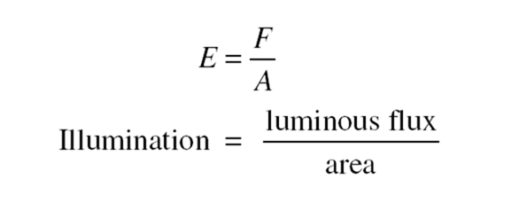
In SI, the unit of illumination is the lumen per square meter, or lux (lx); in the British system, it is the lumen per square foot, or footcandle (fc) (Table 17-1).
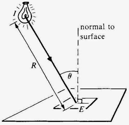
The illumination on a surface a distance R away from an isotropic source of light of intensity I is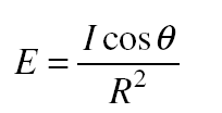
where θ is the angle between the direction of the light and the normal to the surface (Figure 17-3). Thus, the illumination from such a source varies inversely as R2, just as in the case of sound waves; doubling the
distance means, reducing the illumination to ¹⁄₄ its former value. For light
perpendicularly incident on a surface, θ = 0 and cos θ = 1, so in this situation, E = I/R2.
Table 17.1
Solved Problem 17.1 A 10-W fluorescent lamp has a luminous intensity of 35 cd. Find (a) the luminous flux it emits and (b) its luminous efficiency.
When a beam of light is reflected from a smooth, plane surface, the an- gle of reflection equals the angle of incidence (Figure 17-4). The image of an object in a plane mirror has the same size and shape as the object but with left and right reversed; the image is the same distance behind the mirror as the object is in front of it.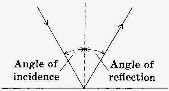
Figure 17-4
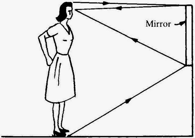
Solved Problem 17.2 A woman 170 cm tall wishes to buy a mirror in which she can see herself at full length. What is the minimum height of such a mirror? How far from the mirror should she stand?
Solution. Since the angle of reflection equals the angle of incidence, the mirror should be half her height (85 cm) and placed so its top is level with the middle of her forehead (Figure 17-5). The distance between the mirror and the woman does not matter.
Refraction of Light
When a beam of light passes obliquely from one medium to another in which its velocity is different, its direction changes (Figure 17-6). The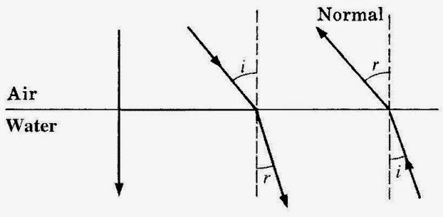
Figure 17-6
greater the ratio between the two velocities, the greater the deflection. If the light goes from the medium of high velocity to the one of low velocity, it is bent toward the normal to the surface; if the light goes the other way, it is bent away from the normal. Light moving along the normal is not deflected.
The index of refraction of a transparent medium is the ratio between the velocity of light in free space c and its velocity in the medium v:
Index of refraction = n = c/v
The greater its index of refraction, the more a beam of light is deflected on entering a medium from air. The index of refraction of air is about 1.0003, so for most purposes, it can be considered equal to 1.
According to Snell’s law, the angles of incidence i and refraction r
shown in Figure 17-6 are related by the formula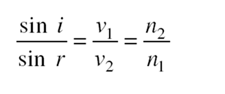
where v1 and n1 are, respectively, the velocity of light and index of re- fraction of the first medium and v2 and n2 are the corresponding quantities in the second medium. Snell’s law is often written
n1 sin i = n2 sin r
In general, the index of refraction of a medium increases with in- creasing frequency of the light. For this reason, a beam of white light is separated into its component frequencies, each of which produces the sensation of a particular color, when it passes through an object whose sides are not parallel, for instance, a glass prism. The resulting band of color is called a spectrum.
Solved Problem 17.3 Why is a beam of white light that passes perpendicularly through a flat pane of glass not dispersed into a spectrum?
Solution. Light incident perpendicular to a surface is not deflected, so light of the various frequencies in white light stays together despite the different velocities in the glass.
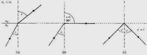
The phenomenon of total internal reflection can occur when light goes from a medium of high index of refraction to one of low index of refraction, for example, from glass or water to air. The angle of refraction in this situation is greater than the angle of incidence, and a light ray is bent away from the normal, as in Figure 17-7(a), at the interface between the two media. At the critical angle of incidence, the angle of refraction is 90° (Figure 17-7(b)), and at angles of incidence greater than this, the refracted rays are reflected back into the original medium (Figure 17-7(c)). If the critical angle is ic,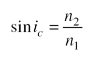
Apparent Depth
An object submerged in water or other transparent liquid appears closer to the surface than it actually is. As Figure 17-8 shows, light leaving the object is bent away from the normal to the water-air surface as it leaves the water. Since an observer interprets what she or he sees in terms of the straight-line propagation of light, the object seems at a shallower depth than its true one. The ratio between apparent and true depths is
where n1 is the index of refraction of the liquid and n2 is the index of re- fraction of air.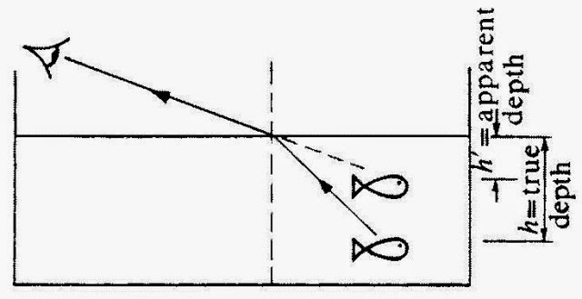
Figure 17-8

