Lenses
In This Chapter:
✔ Focal Length
✔ Ray Tracing
✔ Lens Equation
✔ Magnification
✔ Lens Systems
Focal Length
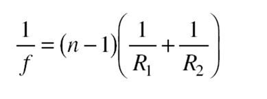
Figure 19-1 shows how a converging lens brings a parallel beam of light to a real focal point F, and Figure 19-2 shows how a diverging lens spreads out a parallel beam of light so that the refracted rays appear to come from a virtual focal point F. In this chapter, we consider only thin lenses, whose thickness can be neglected as far as optical effects are concerned. The focal length f of a thin lens is given by the lensmaker’s equation: In this equation, n is the index of refraction of the lens material relative to the medium it is in, and R1 and R2 are the radii of curvature of the two
Figure 19-1
surfaces of the lens. Both R1 and R2 are considered as plus for a convex (curved outward) surface and as minus for a concave (curved inward) surface; obviously it does not matter which surface is labeled as 1 and which as 2.
A positive focal length corresponds to a converging lens and a neg- ative focal length to a diverging lens.
Figure 19-2
Ray Tracing
As with a spherical mirror, the position and size of the image of an object formed by a lens can be found by constructing a scale drawing by tracing two different light rays from a point of interest in the object to where they (or their extensions, in the case of a virtual image) intersect after being refracted by the lens. Three rays especially useful for this purpose are shown in Figure 19-3; any two are sufficient:
1. A ray that leaves the object parallel to the axis of the lens. After refraction, this ray passes through the far focal point of a con- verging lens or seems to come from the near focal point of a di- verging lens.
2. A ray that passes through the focal point of a converging lens or is directed toward the far focal point of a diverging lens. After refraction, this ray travels parallel to this axis of the lens.
3. A ray that leaves the object and proceeds toward the center of the lens. This ray is not deviated by refraction.
Solved Problem 19.1 What is the nature of the image of a real object formed by a diverging lens?
Solution. It is virtual, erect, and smaller than the object, as in Figure 19-3(b).
Figure 19-3
The object distance p, image distance q, and focal length f of a lens (Fig- ure 19-4) are related by the lens equation:
This equation holds for both converging and diverging lenses. The lens equation is readily solved for p, q, or f :
Figure 19-4
As in the case of mirrors, a positive value of p or q denotes a real object or image, and a negative value denotes a virtual object or image. A real image of a real object is always on the opposite side of the lens from the object, and a virtual image is on the same side. Thus, if a real object is on the left of a lens, a positive image distance q signifies a real image to the right of the lens, whereas a negative image distance q denotes a virtual image to the left of the lens.
Magnification
The linear magnification m produced by a lens is given by the same formula that applies for mirrors:
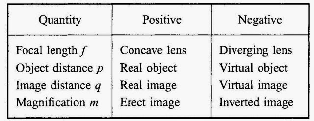
Again, a positive magnification signifies an erect image, a negative one signifies an inverted image. Table 19.1 is a summary of the sign conventions used in connection with lenses.
Solved Problem 18.1 A coin 3 cm in diameter is placed 24 cm from a converging lens whose focal length is 16 cm. Find the location, size, and nature of the image.
Table 19.1
Figure 19-5
Solution. Here p = 24 cm and f = +16 cm, so the image distance is
The image is real since q is positive (Figure 19-5). The diameter of the coin’s image is,
The image is inverted and twice as large as the object.
In general, an object that is a distance between f and 2f from a con- verging lens has a real, inverted image that is larger than the object.
Lens Systems
When a system of lenses is used to produce an image of an object, for in- stance, in a telescope or microscope, the procedure for finding the position and nature of the final image is to let the image formed by each lens in turn be the object for the next lens in the system. Thus, to find the image produced by a system of two lenses, the first step is to determine the image formed by the lens nearest the object. This image then serves as the object for the second lens, with the usual sign convention: If the image is on the front side of the second lens, the object distance is considered positive, whereas if the image is on the back side, the object distance is considered negative.
The total magnification produced by a system of lenses is equal to the product of the magnification of the individual lenses. Thus, if the magnification of the objective lens of a microscope or telescope is m1 and that
of the eyepiece is m2, the total magnification is m = m1m2.

![McGraw-Hill,.Schaum's Easy Outline of Applied Physics Crash Course.[2003.ISBN0071398783]_Page_133_Image_0001 McGraw-Hill,.Schaum's Easy Outline of Applied Physics Crash Course.[2003.ISBN0071398783]_Page_133_Image_0001](http://lh5.ggpht.com/-BYq_Y-ysnxs/VE6L5TC90MI/AAAAAAAAr-w/UfslSM7DMh8/McGraw-Hill%25252C.Schaum%252527s%252520Easy%252520Outline%252520of%252520Applied%252520Physics%252520Crash%252520Course.%25255B2003.ISBN0071398783%25255D_Page_133_Image_0001_thumb.jpg?imgmax=800)
![McGraw-Hill,.Schaum's Easy Outline of Applied Physics Crash Course.[2003.ISBN0071398783]_Page_133_Image_0002 McGraw-Hill,.Schaum's Easy Outline of Applied Physics Crash Course.[2003.ISBN0071398783]_Page_133_Image_0002](http://lh4.ggpht.com/-qFuB_cNd214/VE6L9Z08qwI/AAAAAAAAr_A/CRyk-dP278g/McGraw-Hill%25252C.Schaum%252527s%252520Easy%252520Outline%252520of%252520Applied%252520Physics%252520Crash%252520Course.%25255B2003.ISBN0071398783%25255D_Page_133_Image_0002_thumb.jpg?imgmax=800)
![McGraw-Hill,.Schaum's Easy Outline of Applied Physics Crash Course.[2003.ISBN0071398783]_Page_134_Image_0001 McGraw-Hill,.Schaum's Easy Outline of Applied Physics Crash Course.[2003.ISBN0071398783]_Page_134_Image_0001](http://lh3.ggpht.com/-NqwR0anoxkk/VE6MBZq7hyI/AAAAAAAAr_Q/C8NfFUd3Exc/McGraw-Hill%25252C.Schaum%252527s%252520Easy%252520Outline%252520of%252520Applied%252520Physics%252520Crash%252520Course.%25255B2003.ISBN0071398783%25255D_Page_134_Image_0001_thumb.jpg?imgmax=800)
![McGraw-Hill,.Schaum's Easy Outline of Applied Physics Crash Course.[2003.ISBN0071398783]_Page_135_Image_0001 McGraw-Hill,.Schaum's Easy Outline of Applied Physics Crash Course.[2003.ISBN0071398783]_Page_135_Image_0001](http://lh6.ggpht.com/-YHF8Zw1W6q4/VE6MLaOuWxI/AAAAAAAAsAA/XmPPKGKQ0u8/McGraw-Hill%25252C.Schaum%252527s%252520Easy%252520Outline%252520of%252520Applied%252520Physics%252520Crash%252520Course.%25255B2003.ISBN0071398783%25255D_Page_135_Image_0001_thumb%25255B1%25255D.jpg?imgmax=800)

![McGraw-Hill,.Schaum's Easy Outline of Applied Physics Crash Course.[2003.ISBN0071398783]_Page_133_Image_0001 McGraw-Hill,.Schaum's Easy Outline of Applied Physics Crash Course.[2003.ISBN0071398783]_Page_133_Image_0001](http://lh4.ggpht.com/-dENlYY-45g0/VE6MWJlJyOI/AAAAAAAAsAw/phQsC-rKJ5Q/McGraw-Hill%25252C.Schaum%252527s%252520Easy%252520Outline%252520of%252520Applied%252520Physics%252520Crash%252520Course.%25255B2003.ISBN0071398783%25255D_Page_133_Image_0001_thumb%25255B1%25255D.jpg?imgmax=800)
