Should be referred to as an RC servo if it is intended for use in small devices that are remote-controlled and battery powered. However, in practice, the RC acronym is often omitted.
What It Does
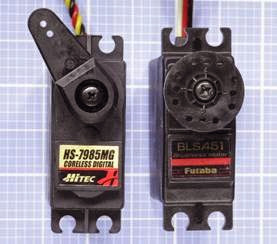
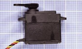
A servo motor is actually a combination of a motor, reduction gearing, and miniaturized control electronics, usually packaged together inside a very compact sealed plastic case. The motor itself may be AC or DC, and if DC, it may be brushed or brushless. What distinguishes a servo from other types of motor is that it is not designed for continuous rotation. It is a position-seeking device. Its rotational range may be more than 180 degrees but will be significantly less than 360 degrees. Two typical RC servos are shown in Figure 24-1. A side view of a motor is shown in Figure 24-2.
The electronics inside the motor enclosure interpret commands from an external controller. The command code specifies the desired turn angle measured as an offset either side of the center position of the motor’s range. The motor turns quickly to the specified position and stops there. So long as the command signal continues and power to the motor is sustained, the motor will hold its position and “push back” against any external turning force. In the absence of such a force, while the motor is stationary, it will use very little current.
Figure 24-1. A typical RC servo motor is capable of more than 50 inch-ounces of torque yet can be driven by three or four AA alkaline cells in series, and weighs under 2 oun- ces.
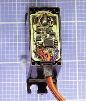
The electronics inside a typical RC servo motor are shown in Figure 24-3.
How It Works
Servo motors are generally controlled via pulse- width modulation (PWM).
Figure 24-2. RC servo motors are mostly similar in size. This is a typical side view.
An industrial servo typically requires a controller that is an off-the-shelf item sold by the manufacturer of the motor. The encoding scheme of the control signals may be proprietary. A heavy- duty servo may be designed to run from three- phase power at a relatively high voltage, and may be used in applications such as production-line automation.
The remainder of this encyclopedia entry will focus primarily on small RC servos rather than in dustrial servos.
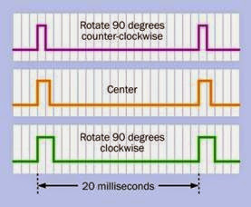
For small RC servos, the stream of control pulses is at a constant frequency of 20ms, with the positive durations of each pulse being interpreted as a positioning command to the motor, and the gaps between the pulses being disregarded. A typical range of pulse widths for a small motor is 1ms to 2ms, specifying a range of -90 to +90 de grees either side of a center location. Many modern motors are capable of excursions be yond these limits, and can be calibrated to establish the precise relationship between pulse width and turn angle. The motor can then be controlled by a lookup table in microcontroller software, or by using a conversion factor be tween degree-angle and pulse width.
Figure 24-4 shows the typical range of pulse widths within the fixed 20ms period (a frequency of 50Hz) between the start of one pulse and the
start of the next, and the meaning of each pulse width to the servo motor. Intermediate pulse widths are interpreted as instructions to rotate to intermediate positions.
Figure 24-3. The electronics inside a servo motor decode a stream of pulses that specify the turn angle of the motor.
Small servo motors require the user to provide a controller that will conform with the above spec ification. This is often achieved by programming a microcontroller, and some microcontroller chips make this especially easy by providing a PWM output specifically tailored to the require ments of an RC servo. Either way, the microcontroller can be directly connected to the servo, enabling an extremely simple and flexible way to manage a positioning device.
Alternatively, a simple pulse generator such as a 555 timer chip can be used, or controller boards are available from hobbyist supply sources. Some controller boards have USB connections enabling a servo to be governed by computer software.
Figure 24-4. The turn angle of a small RC servo motor is determined by a pulse width from a controller ranging from 1ms to 2ms in duration. The frequency of the pulses is constant at 50Hz.
In Figure 24-5, a schematic illustrates the connection of a 555 timer with an RC servo, with component values to create a constant frequen cy of about 48Hz (slightly more than 20ms from peak to peak). The 1μF capacitor in the circuit charges through the 2.2K resistor in series with the diode, which bypasses the 28K resistor. This charging time represents the “on” cycle of the timer chip. The capacitor discharges through the 28K resistor, representing the “off” cycle. The 1K potentiometer, in series with the 5K resistors, acts as a voltage divider applied to the control pin of the timer, adjusting the timer’s charge and dis charge thresholds. Turning the potentiometer will lengthen or shorten the “on” time of each cycle, without changing the frequency. In prac tice, because capacitors are manufactured with wide tolerances, the frequency of the timer out put cannot be guaranteed. Fortunately most servos will tolerate some inaccuracy.
Since the motor shares the power supply of the timer in this circuit, a protection diode and capacitor have been added between the power supply to the motor and negative ground, to suppress noise and back-EMF.
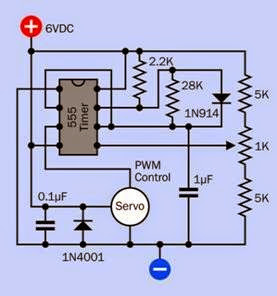 Figure 24-5. An RC servo can be controlled via a 555 timer with appropriate component values. The potentiometer determines the angular position of the servo.
Inside a servo motor’s casing, the electronics in clude a potentiometer that turns with the output shaft, to provide feedback confirming the motor’s position. The limited turning range of the potentiometer determines the turn limits of the motor output shaft.
Variants
Small servos may contain brushed or brushless DC motors. Naturally the brushless motors have greater longevity and create less electrical noise. See the DC motor entry in this encyclopedia for a discussion of brushed versus brushless motors.
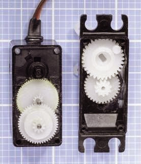
Servos may use nylon, “Karbonite,” or metal re duction gearing. The nylon gears inside a cheap er RC servo are shown in Figure 24-6.
Brushless motors and metal gears add slightly to the price of the motor. Metal gears are stronger than nylon (which can crack under load) but may wear faster, leading to backlash and inaccuracy in the gear train. The friction between nylon-to- nylon surfaces is very low, and nylon is certainly
Figure 24-6. Nylon gearing inside a servo motor.
adequate and may be preferable if a servo will not be heavily loaded. “Karbonite” is claimed to be five times stronger than nylon and may be a satisfactory compromise. If a gear set experiences a failure (for example, teeth can be stripped as a result of excessive load), manufacturers usually will sell a replacement set to be installed by the user. Installation requires manual dexterity and patience, and some skill.
Servos may have roller bearings or plain sintered bearings, the latter being cheaper but much less durable under side loading.
So-called digital servos use faster internal electronics than the older, so-called analog servos, and because they sample the incoming pulse stream at a higher frequency, they are more re sponsive to small, rapid commands from the controller. For this reason they are preferred by hob byists using servos to control the flight of model airplanes. Externally, the control protocol for dig ital and analog servos is the same, although a
digital servo can be reprogrammed with new code values establishing the limits to its range. A standalone programming unit must be purchased to achieve this.
The most popular manufacturers of small servo motors are Futaba and Hitec. While their control protocols are virtually identical, the motor out put shafts differ. The shaft is typically known as the spline, and is grooved to fit push-on attach ments. The spline of a Futaba motor has 25 grooves, while Hitec uses 24 grooves. Attach ments must be appropriate for the brand of mo tor that has been chosen.
Values
A small servo typically weighs 1 to 2 ounces, has a rotation time of 1 to 2 seconds from one end of its travel to the other, and can exert a surprisingly robust torque of 50 ounce-inches or greater.
Voltage
Small servos were originally designed to run from 4.8V rechargeable batteries in model aircraft. They can be driven with 5VDC to 6VDC on a routine basis. A few servos are designed for higher voltages.
Amperage
The datasheets provided by most manufacturers often fail to specify the power that a servo will draw when it is exerting maximum torque (or indeed, any torque at all). Since small servos are often driven by three or four AA alkaline batteries in series, the maximum current draw is unlikely to be much greater than 1 amp. When the motor is energized but not turning, and is not resisting a turning force, its power consumption is negligible. This feature makes servos especially desirable for remote-controlled battery-powered devices.
Some motors that have a turning range exceeding 180 degrees will respond to pulses of less than 1ms or greater than 2ms. A newly acquired motor should be tested with a microcontroller
that steps through a wide range of pulse durations, to determine the limits empirically. Pulses that are outside the motor’s designed range will generally be ignored and will not cause damage.
The turn rate or transit time specified in a data sheet is the time a servo takes to rotate through 60 degrees, with no load on the output shaft. A high-torque servo generally achieves its greater turning force by using a higher reduction gear ratio, which tends to result in a longer transit time.
How to Use it
Typical applications for a small servo include rotating the flaps or rudder of a model aircraft, steering a model boat, model car, or wheeled robot, and turning robotic arms.
A servo generally has three wires, colored red (power supply), black or brown (ground), and orange, yellow, or white (for the pulse train from the controller). The ground wire to the motor must be common with the ground of the controller, and consequently a ceramic bypass capacitor of 0.1μF or 0.01μF should be placed be tween the (red) power wire to the motor and ground. A protection diode should also be used. Neither a diode nor a capacitor should be attached to the wire carrying control signals, as it will interfere with the pulse train.
When powering the motor, an AC adapter should only be used with some caution, as its power output may be inadequately smoothed. A volt age regulator is not necessary, but bypass capacitors are mandatory. Figure 24-7 shows two hypothetical schematics. The upper section of the figure shows a battery-driven system, possibly using four 1.2V NiMH rechargeable batteries. Since batteries do not generally create voltage spikes, no capacitors are used, but a diode is included to protect the microcontroller from EMF when the servo stops and starts. The lower section of the figure shows the additional precautions that may be necessary when using DC power from an AC adapter. The DC-DC converter,
which derives 6VDC for the motor requires smoothing capacitors (this should be specified in its datasheet), and so does the voltage regulator, which delivers regulated 5VDC power to the microcontroller. Once again, the protection diode is included. In both diagrams, the orange wire represents the control wire transmitting pulses to the servo motor.
Figure 24-7. Two possible schematics to run a small servo motor, the upper example using battery power (for example, from four 1.2V NiMH cells) and the lower example us- ing a 9VDC AC adapter. See text for additional explanation.
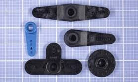
Various shaft attachments are available from the same online hobby-electronics suppliers that sell servos. The attachments include discs, single arms, double arms, and four arms in a cross- shaped configuration. A single-arm attachment is often known as a horn, and this term may be applied loosely to any kind of attachment. The
horn is usually perforated so that other components can be fixed to it by using small screws or nuts and bolts. Figure 24-8 shows a variety of horns.
Figure 24-8. Various shaft attachments, known as horns, are available from motor manufacturers. The blue one is metallic; the others are plastic.
After the horn is pushed onto the spline (the motor shaft), it is held in place with one central screw. As previously noted, the two major man ufacturers of small servos, Futaba and Hitec, have incompatible splines.
Modification for Continuous Rotation
It is possible to modify a small servo motor so that it will rotate continuously.
First the motor case must be opened, and the potentiometer must be centered by using a controller to send some 1.5ms pulses. The potentiometer must then be glued or otherwise secured with its wiper in this precise center position, after which the potentiometer is disconnected from the drive train.
Mechanical stops that would limit the rotation of the motor shaft must be cut away, after which the motor is reassembled. Because the potentiometer has been immobilized, the motor’s inter nal electronics will now “see” the shaft as being in its center position at all times. If the controller sends a pulse instructing the motor to seek a position clockwise or counter-clockwise from cen ter, the motor will rotate in an effort to reach that
position. Because the potentiometer will not provide feedback to signal that the motor has achieved its goal, the shaft will continue to rotate indefinitely.
In this mode, the primary distinguishing characteristic of the servo has been disabled, in that it can no longer turn to a specific angle. Also, stop ping the servo may be problematic, as it must receive a command that precisely matches the fixed position of the potentiometer. Since the potentiometer may have moved fractionally during the process in which it was immobilized, some trial and error may be needed to determine the pulse width that corresponds with the potentiometer position.
The purpose of modifying a servo for continuous rotation is to take advantage of its high torque, small size, light weight, and the ease of control ling it with a microcontroller.
In response to the interest shown by hobbyists in modifying servos for continuous rotation, some manufacturers now market servos with continuous rotation as a built-in feature. Typical ly they include a trimmer potentiometer to cali brate the motor, to establish its center-off position.
What Can Go Wrong
Incorrect Wiring
The manufacturer’s datasheet should be checked to confirm the color coding of the wires. While a simple DC motor can be reversed by in verting the polarity of its power supply, this is totally inappropriate for a servo motor.
Shaft/Horn Mismatch
Attachments for the spline of one brand of motor may not fit the spline of another brand, and can not be forced to fit.
Unrealistically Rapid Software Commands
Microcontroller software that positions a servo must allow sufficient time for the servo to respond before the software specifies a new posi tion. It may be necessary to insert delay loops or other wait times in the software.
Jitter
A servo arm that twitches unpredictably usually indicates that the pulse train is being corrupted by external electrical noise. The control wire to the servo should be as short as possible, and should not run closely adjacent to conductors carrying AC or high frequency current switching, or control wires for other servo motors.
Motor Overload
A servo capable of delivering 2 lbs of force 1 inch from its shaft can easily generate enough torque, when it stalls, to break itself free from its mounts, or bend or break any arm or linkage attached to its shaft. Ideally, a relatively “weak link” should be included so that if breakage occurs, it will be predictable and will be relatively easy and cheap to repair.
Unrealistic Duty Cycle
Small servos are designed for intermittent use. Constant cycling will cause wear and tear, especially if the motor has a brushed commutator or metal reduction gears.
Electrical Noise
Brushed motors are always a source of electrical interference, and any servo will also tend to create a voltage dip or surge when it starts and stops. A protection diode may be insufficient to isolate sensitive microcontrollers and other integrated circuit chips. To minimize problems, the servo can be driven by a source of positive volt age that is separate from the regulated power supply used by the chips, and larger filter capacitors may be added to the voltage supply of the microcontroller. A common ground between the motor and the chips is unfortunately unavoidable.

