The distinction between AC and DC motors has become blurred as controllers for DC motors make increasing use of pulse-width modulation, which can be viewed as a form of alternating current. All motors that consume DC power are referenced in the DC motor section of this encyclopedia, regardless of whether they modulate the power internally. Stepper motors and servo motors are considered as special cases, each with its own entry. AC motors, described here, are those that consume alternating current, usu ally in the form of a sine wave with a fixed frequency.
What It Does
An AC motor uses a power supply of alternating current to generate a fluctuating magnetic field that turns a shaft.
How It Works
The motor consists primarily of two parts: the stator, which remains stationary, and the rotor, which rotates inside the stator. Alternating cur rent energizes one or more coils in the stator, creating fluctuating magnetic fields that interact with the rotor. A simplified representation is shown in Figure 23-1, where the coils create mag netic forces indicated by the green arrows, N rep resenting North and S representing South.
Stator Design
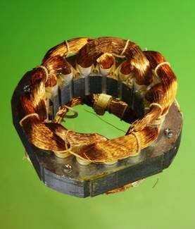
Plug-in electric fans typically use AC motors. The stator from a large electric fan is shown in Figure 23-2, where the large diameter of each coil
Figure 23-1. A simplified representation of a basic AC motor. The green arrows indicate magnetic force.
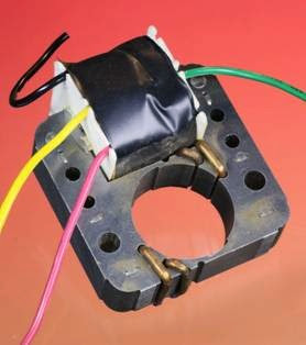
maximizes its magnetic effect. The stator from a smaller electric fan is shown in Figure 23-3, in which only one coil is used. (The coil is wrapped in black electrical tape.)
Figure 23-2. The stator from a large electric fan. Each coil of copper wire is centered on a lug pointing inward to the hole at the center, where the rotor would normally be mounted. The coils overlap because their diameter is maximized to increase their magnetic effect. Each coil is tapped to allow speed selection in steps via an external rotary switch.
The core of a stator resembles the core of a transformer in that it usually consists of a stack of wafers of high-silicon steel (or sometimes aluminum or cast iron). The layers are insulated from one another by thin layers of shellac (or a similar compound) to prevent eddy currents that would otherwise circulate through the entire thickness of the stator, reducing its efficiency.
The coil(s) wound around the stator are often re ferred to as field windings, as they create the magnetic field that runs the motor.
Rotor Design
In most AC motors, the rotor does not contain any coils and does not make any electrical con
Figure 23-3. This stator from a smaller electric fan uses only a single coil, wrapped in black tape. It is sufficient to induce a magnetic field but is generally less efficient than a motor using multiple coils.
nection with the rest of the motor. It is powered entirely by induced magnetic effects, causing this type of motor to be known generally as an induction motor.
As the AC voltage changes from positive to negative, the magnetic force induced in the stator collapses and a new field of opposite polarity is created. Because the stator is designed to create an asymmetrical field, it induces a rotating magnetic field in the rotor. The concept of a rotating magnetic field is fundamental in AC motors.
Like the stator, the rotor is fabricated from wafers of high silicon steel; embedded in the wafers are nonmagnetic rods, usually fabricated from aluminum but sometimes from copper, oriented approximately parallel to the axis of rotation. The rods are shorted together by a ring at each end of the rotor, forming a conductive “cage,” which explains why this device is often referred to colloquially as a squirrel cage motor.
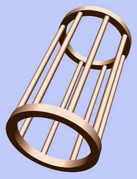
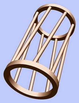
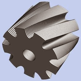
Figure 23-4 shows the configuration of a rotor cage with the surrounding steel wafers removed for clarity. In reality, the rods in the cage are al most always angled slightly, as shown in Figure 23-5, to promote smooth running and re duce cogging, or fluctuations in torque, which would otherwise occur.
Figure 23-4. The rotor of a typical AC motor contains a cage of aluminum (or sometimes copper) in which eddy currents occur, as a result of the rotating magnetic field inside the steel body of the rotor (which is omitted here for clarity). These currents cause their own magnetic fields, which interact with the fields generated by coils in the stator.
In Figure 23-6, the steel wafers of a rotor are shown, with channels to accommodate an angled aluminum cage. Figure 23-7 shows a cross- section of a rotor with the cage elements in pale red and the steel wafer in gray.
Figure 23-5. To promote smooth running of the motor, the longitudinal elements of the cage are typically angled, as suggested in this rendering.
Figure 23-6. The steel wafers in the rotor of an AC motor are typically offset as shown here. The channels are to ac- commodate a cage of aluminum or copper conductors.
Figure 23-7. Cross-section of a rotor with steel shown in gray and embedded elements of an aluminum cage shown in pale red.
The actual rotor from an induction motor is shown in Figure 23-8. This rotor was removed from the stator shown in Figure 23-3. The bear ings at either end of the rotor were bolted to the stator until disassembly.
Although the cage is nonmagnetic, it is electrically conductive. Therefore the rotating magnetic field that is induced in the steel part of the rotor generates substantial secondary electric current in the cage, so long as the magnetic field inside the rotor is turning faster than the rotor itself. The current in the longitudinal elements of the cage creates its own magnetic field, which interacts with the fields created by coils in the stator. At traction and repulsion between these fields causes the rotor to turn.
Note that if the turning speed of the rotor rises to match the frequency of the alternating current powering the coils in the stator, the cage in the rotor is no longer turning through magnetic lines of force, and ceases to derive any power from
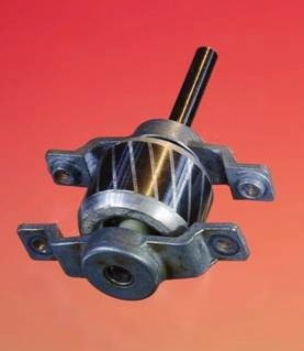 Figure 23-8. The rotor from a small fan motor. The aluminum cage and its end pieces are the pale gray sections, steel plates are the darker sections.
them. In an ideal, frictionless motor, its unloaded operating speed would be in equilibrium with the AC frequency. In reality, an induction motor never quite attains that speed.
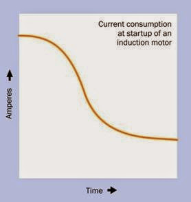
When power is applied while the rotor is at rest, the induction motor draws a heavy surge of cur rent, much like a short-circuited transformer. Electrically, the coils in the stator are comparable to the primary winding of a transformer, while the cage in the rotor resembles the secondary winding. The turning force induced in the stationary rotor is known as locked-rotor torque. As the motor picks up speed, its power consumption diminishes. See Figure 23-9.
When the motor is running and a mechanical load is applied to it, the motor speed will drop. As the speed diminishes, the cage of conductors embedded in the rotor will derive more power, as they are turning more slowly than the rotating magnetic field. The speed of rotation of the field is determined by the frequency of the AC power, and is therefore constant. The difference in rota
Figure 23-9. An approximated graph showing the typical current consumption of an AC induction motor as it starts from rest and gains speed over a period of time.
tional speed between the magnetic field and the rotor is known as slip. Higher levels of slip induce greater power, and therefore the induction motor will automatically find an equilibrium for any load within its designed range.
When running under full load, a small induction motor may have a slip value from 4 to 6 percent. In larger motors, this value will be lower.
Variants
Variants of the generic induction motor de scribed above are generally designed to take ad vantage of either single-phase or three-phase al ternating current.
A synchronous motor is a variant in which the ro tor maintains a constant speed of rotation regardless of small fluctuations in load.
Some AC motors incorporate a commutator, which allows an external connection to coils mounted on the rotor, and can enable variable speed control.
A linear motor may consist of two rows of coils, energized by a sequence of pulses that can move a permanent magnet or electromagnet between the coils. Alternatively, the linear motor’s coils may move as a result of magnetic interaction with a segmented fixed rail. Detailed description of linear motors is outside the scope of this en cyclopedia.
Single-Phase Induction Motor
The majority of induction motors run on single- phase alternating current (typically, from domes tic wall outlets). This type of motor is not innately self-starting because the stator coils and rotor are symmetrical. This tends to result in vibration rather than rotation.
To initiate rotation, the stator design is modified so that it induces an asymmetrical magnetic field, which is more powerful in one direction than the other. The simplest way to achieve this is by adding one or more shorting coils to the stator. Each shorting coil is often just a circle of heavy- gauge copper wire. This ploy reduces the efficiency of the motor and impairs its starting tor que, and is generally used in small devices such as electric fans, where low-end torque is unimportant. Because the shorting coil obstructs some of the magnetic field, this configuration is often known as a shaded pole motor.
Copper shorting coils are visible in the fan motor shown in Figure 23-3.
A capacitor is a higher-cost but more efficient alternative to a shorting coil. If power is supplied to one or more of the stator coils through a capacitor, it will create a phase difference between these coils and the others in the motor, inducing an asymmetrical magnetic field. When the motor reaches approximately 80% of its designed running speed, a centrifugal switch may be included to take the capacitor out of the circuit, since it is no longer necessary. Switching out the capacitor and substituting a direct connection to the stator coils will improve the efficiency of the motor.
A third option to initiate rotation is to add a second winding in the stator, using fewer turns of smaller-gauge wire, which have a higher resist ance than the main winding. Consequently the magnetic field will be angled to encourage the motor to start turning. This configuration is known as a split-phase induction motor, in which the starter winding is often referred to as the auxilliary winding and consists of about 30% of the total stator windings in the motor. Here again, a centrifugal switch can be incorporated, to eliminate the secondary winding from the circuit when the motor has reached 75 to 80 per cent of its designed running speed.
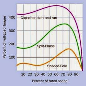
The relationship between motor speed and torque of the three types of motors described above is shown in Figure 23-10. These curves are simplified and do not show the effect that would be produced by introducing a centrifugal switch.
Figure 23-10. Approximate curves showing the relation- ship between speed and torque for three types of single- phase induction motor. (Graph derived from AC Induction Motor Fundamentals published by Microchip Technology Inc.)
Three-Phase Induction Motor
Larger induction motors are often three-phase
devices. Three-phase AC (which is by far the most
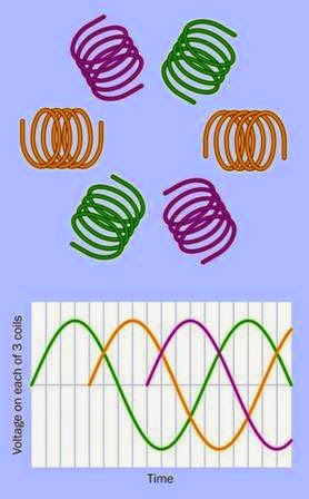
common form of polyphase AC) is delivered by a power utility company or generator via three wires, each of which carries alternating current with a phase difference of 120 degrees relative to the other two, usually for industrial applica tions. A common configuration of stator coils for a three-phase motor is shown in Figure 23-11. Since the three wires take it in turns to deliver their peak voltage, they are ideally suited to turn the stator of a motor via induction, and no shorting coil or capacitor is needed for startup. Heavy- duty 3-phase induction motors are extremely re liable, being brushless and generally maintenance-free.
Synchronous Motor
A synchronous motor is a form of induction mo tor that is designed to reach and maintain equilibrium when the rotor is turning in perfect syn chronization with the AC power supply. The speed of the motor will depend on the number of poles (magnetic coils) in the stator, and the number of phases in the power supply. If R is the RPM of a synchronous motor, f is the frequency of the AC current in Hz, and p is the number of poles per phase:
R = (120 * f) / p
This formula assumes 60Hz AC current. In nations where 50Hz AC is used, the number 120 should be replaced with the number 100.
Two basic types of synchronous motors exist: di rect current excited, which require external power to start turning, and non-excited, which are self- starting. Since non-excited synchronous motors are more common in electronic applications, this encyclopedia will not deal with direct current ex cited variants.
A hysteresis motor is a synchronous motor con taining a solid rotor cast from cobalt steel, which has high coercivity, meaning that once it is mag netized, a substantial field is required to reverse the magnetic polarity. Consequently the polarity of the rotor lags behind the constantly changing
Figure 23-11. The graph shows voltage delivered via three wires constituting a three-phase power supply. (The curve colors are arbitrary.) A three-phase motor contains a multiple of three coils—often six, as shown here diagrammatically. The three wires of the power supply are connected directly to the coils, which induce a rotating magnetic field.
polarity of the stator, creating an attracting force that turns the rotor. Because the lag angle is in dependent of motor speed, this motor delivers constant torque from startup.
Reluctance Motor
Reluctance is the magnetic equivalent to electrical resistance. If a piece of iron is free to move in a magnetic field, it will tend to align itself with the field to reduce the reluctance of the magnetic
circuit. This principle was used in very early reluctance motors designed to work from AC and has been revived as electronics to control variable frequency drives have become cheaper.
The simplest reluctance motor consists of a soft iron rotor with projecting lugs, rotating within a stator that is magnetically energized with its own set of inwardly projecting poles. The rotor tends to turn until its lugs are aligned with the poles of the stator, thus minimizing the reluctance.
A basic reluctance motor design is shown in Figure 25-2. It is located in the stepper motor section of this encyclopedia, as stepper motors are a primary application of the reluctance principle.
Although a reluctance motor can be used with polyphase fixed-frequency AC power, a variable frequency drive greatly enhances its usefulness. The timing of the frequency is adjusted by the speed of the motor, which is detected by a sensor. Thus the energizing pulses can remain “one step ahead” of the rotor. Since the rotor is not a mag net, it generates no back-EMF, allowing it to reach very high speeds.
The simplicity of the motor itself is a compensating factor for the cost of the electronics, as it re quires no commutator, brushes, permanent magnets, or rotor windings. Characteristics of re luctance motors include:
• Cheap parts, easily manufactured, and high reliability.
• Compact size and low weight.
• Efficiencies greater than 90% possible.
• Capable of high start-up torque and high speed operation.
Disadvantages include noise, cogging, and tight manufacturing tolerances, as the air gap be tween the rotor and stator must be minimized.
A reluctance motor can function synchronously, if it is designed for that purpose.
Variable Frequency Drive
A basic induction motor suffers from significant problems. The surge of power that it draws when starting from rest can pull down the supply volt age enough to affect other devices that share the AC power supply. (Hence, the brief dimming of lights that may occur when the compressor in an air conditioner or refrigerator starts running.) While the motor is turning, it can introduce electrical noise, which feeds back into the power supply, once again causing potential problems for other devices. In addition, the narrow range of speed of an AC induction motor is a great dis advantage.
The advent of cheap solid-state technology encouraged the development of variable-frequency power supplies for induction motors. Because the impedance of the motor will diminish as the frequency diminishes, the current drawn by the motor will tend to increase. To prevent this, a variable frequency supply also varies the voltage that it delivers.
Wound-Rotor AC Induction Motor
The stator of this variant is basically the same as that of a single-phase induction motor, but the rotor contains its own set of coils. These are electrically accessible via a commutator and brushes,
as in a DC motor. Because the maximum torque
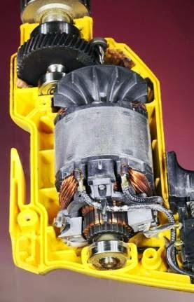
(also known as pull-out torque) will be prop or tional to the electrical resistance of the coils in the rotor, the characteristics of the motor can be adjusted by adding or removing resistance externally, via the commutator. A higher resistance will enable greater torque at low speed when the slip between the rotor speed and rotation of the magnetic field induced by the stator is greatest. This is especially useful in corded power tools such as electric drills, where high torque at low speed is desirable, yet the motor can accelerate to full speed quickly when the external resistance is reduced. Typically, the resistance is adjusted via the trigger of the drill.
Figure 23-12 shows a wound-rotor AC induction motor. The disadvantage of this configuration is
the brushes that supply power to the rotor will eventually require maintenance. Much larger wound-rotor motors are also used in industrial applications such as printing presses and eleva tors, where the need for variable speed makes a simple three-phase motor unsuitable.
Figure 23-12. A motor in a corded electric drill uses coils in a brushed rotor to enable variable speed output. In most AC motors, the speed is not adjustable and the rotor does not make any electrical connection with the rest of the motor.
Universal Motor
A wound-rotor motor may also be described as a universal motor if its rotor and stator coils are connected in series. This configuration allows it to be powered by either AC or DC.
DC supplied to the rotor and the stator will cause mutual magnetic repulsion. When the rotor
turns, the brushes touching the split commutator reverse the polarity of voltage in the rotor coils, and the process repeats. This configuration is very similar to that of a conventional DC motor, except that the stator in a universal motor uses electromagnets instead of the permanent mag nets that are characteristic of a DC motor.
When powered by AC, the series connection be tween stator and rotor coils insures that each pulse to the stator will be duplicated in the rotor, causing mutual repulsion. The addition of a shorting coil in the stator provides the necessary asymmetry in the magnetic field to make the motor start turning.
Universal motors are not limited by AC frequency, and are capable of extremely high-speed operation. They have high starting torque, are com pact, and are cheap to manufacture. Applications include food blenders, vacuum cleaners, and hair dryers. In a workshop, they are found in routers and miniature power tools such as the Dremel series.
Because a universal motor requires commutator and brushes, it is only suitable for intermittent use.
Inverted AC Motors
Some modern domestic appliances may seem to contain an AC motor, but in fact the AC current is rectified to DC and is then processed with pulse-width modulation to allow variable speed control. The motor is really a DC motor; see the entry on this type of motor for additional information.
Values
Because a basic AC induction motor is governed by the frequency of the power supply, the speed of a typical four-pole motor is limited to less than 1,800 RPM (1,500 RPM in nations where 50Hz AC is the norm).
Variable-frequency, universal, and wound-rotor motors overcome this limitation, and can reach
speeds of 10,000 to 30,000 RPM. Synchronous motors typically run at 1,800 or 1,200 RPM, de pending on the number of poles in the motor. (They run at 1,500 or 1,000 RPM in locations where the frequency of AC is 50Hz rather than 60Hz).
For a discussion of the torque that can be created by a motor, see “Values” (page 184) in the DC motor entry in this encyclopedia.
How to Use It
Old-fashioned record players (where a turntable supports a vinyl disc that must rotate at a fixed speed) and electric clocks (of the analogue type) were major applications for synchronous motors, which used the frequency of the AC power sup ply to control motor speed. These applications have been superceded by CD players (usually powered by brushless DC motors) and digital clocks (which use crystal oscillators).
Many home appliances continue to use AC- powered induction motors. Small cooling fans for use in electronic equipment are sometimes AC-powered, reducing the current that must be provided by the DC power supply. An induction motor generally tends to be heavier and less ef ficient than other types, and its speed limit im posed by the frequency of the AC power supply is a significant disadvantage.
A simple induction motor cannot provide the so phisticated control that is necessary in modern devices such as CD or DVD players, ink-jet printers, and scanners. A stepper motor, servo mo tor, and DC motors controlled with pulse-width modulation are preferable in these applications.
A reluctance motor may find applications in high- speed, high-end equipment including vacuum cleaners, fans, and pumps. Large variable reluctance motors, with high amperage ratings, may be used to power vehicles. Smaller variants are being used for power steering systems and wind shield wipers in some automobiles.
What Can Go Wrong
Compared with other devices that have moving parts, the brushless induction motor is one of the most reliable and efficient devices ever invented. However, there are many ways it can be dam aged. General problems affecting all types of motors are listed at “Heat effects” (page 188). Is sues relating specifically to AC motors are listed below.
Premature Restart
Large industrial three-phase induction motors can be damaged if power is reapplied before the motor has stopped rotating.
Frequent Restart
If a motor is stopped and started repeatedly, the heat that is generated during the initial surge of current is likely to be cumulative.
Undervoltage or Voltage Imbalance A voltage drop can cause the motor to draw more current than it is rated to handle. If this situation persists, overheating will result. Problems also
are caused in a three-phase motor where one
phase is not voltage-balanced with the others. The most common cause of this problem is an open circuit-breaker, wiring fault, or blown fuse affecting just one of the three conductors. The motor will try to run using the two conductors that are still providing power, but the result is likely to be destructive.
Stalled Motor
When power is applied to an induction motor, if the motor is prevented from turning, the con ductors in the rotor will carry a large current that is entirely dissipated as heat. This current surge will either burn out the motor or blow a fuse or circuit breaker. Care should be taken, in equip ment design, to minimize the risk that an induction motor may stall or jam.
Protective Relays
Sophisticated protective relays are available for industrial 3-phase motors, and can guard against all of the faults itemized above. Their details are outside the scope of this encyclopedia.
Excess Torque
As has been previously noted, the torque of an induction motor increases with the slip (speed difference) between the rotation of the magnetic field and the rotation of the rotor. Consequently, if the motor is overloaded and forced to run more slowly, it can deliver more rotational force. This can destroy other parts attached to the motor, such as drive belts.
Internal Breakage
An overloaded induction motor may suffer some cracking or breakage of its rotor. This may be ob vious because of reduced power output or vi bration, but can also be detected if the motor’s power consumption changes significantly.


