switch What It Does,How It Works ,Variants,Values,How to Use it and What Can Go Wrong


The term switch refers here to a physically operated mechanical switch, controlled by flipping a lever or sliding a knob. Although there is some overlap of function, rotary switches and pushbuttons have their own separate entries. Solid-state switching com­ponents are described in entries for bipolar transistor, unijunction transistor, and field-effect transistor. Integrated-circuit switching devices will be found in Volume 2. Coaxial switches are used for high-frequency signals, and are not included in this ency­clopedia. Multidirectional switches differentiate up, down, left, right, diagonal, rotational, and other finger inputs, and are not included in this encyclopedia.

What It Does

A switch contains at least two contacts, which close or open when an external lever or knob is flipped or moved. Schematic symbols for the most basic type of on-off switch are shown in Figure 6-1.

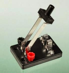
The most fundamental type of switch is a knife switch, illustrated in Figure 6-2. Although it was common in the earliest days of electrical discov­ery, today it is restricted to educational purposes in schools, and (in a more robust format) to AC electrical supply panels, where the large contact area makes it appropriate for conducting high amperages, and it can be used for “hot switching” a substantial load.

How It Works

The pole of a switch is generally connected with a movable contact that makes or breaks a con­nection with a secondary contact. If there is only one pole, this is a single-pole switch. If there is an additional pole, electrically isolated from the

clip_image004

Figure 6-1. The two most common schematic symbols for a SPST switch, also known as an on-off switch. The symbols are functionally identical.

first, with its own contact or set of contacts, this is a two-pole switch, also known as a double- pole switch. Switches with more than 4 poles are uncommon.

If there is only one secondary contact per pole, this is a single-throw or ST switch, which may also be described as an on-off or off-on switch. If there is an additional secondary contact per pole, and the pole of the switch connects with the second contact while disconnecting from the first, this is a double-throw or DT switch, also known as a two– way switch.

clip_image007

Figure 6-2. A DPST knife switch intended for the educational environment.

A double-throw switch may have an additional center position. This position may have no con­nection (it is an “off” position) or in some cases it connects with a third contact.

Where a switch is spring-loaded to return to one of its positions when manual pressure is released, it functions like a pushbutton even though its physical appearance may be indistinguishable from a switch.

Variants

Float switch, mercury switch, reed switch, pressure switch, and Hall-effect switch are considered as sensing devices, and will be found in Volume 3.

Terminology

Many different types of switches contain parts that serve the same common functions. The ac­tuator is the lever, knob, or toggle that the user turns or pushes. A bushing surrounds the actua­ tor on a toggle-type switch. The common con­ tact inside a switch is connected with the pole of

the switch. Usually a movable contact is attached to it internally, to touch the secondary contact, also known as a stationary contact when the movable contact is flipped to and fro.

Poles and Throws

Abbreviations identify the number of poles and contacts inside a switch. A few examples will make this clear:

SPST also known as 1P1T

Single pole, single throw

DPST also known as 2P1T

Double pole, single throw

SPDT also known as 1P2T

Single pole, double throw

3PST also known as 3P1T

Three pole, single throw

Other combinations are possible.

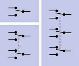
In Figure 6-3, schematic symbols are shown for double-throw switches with 1, 2, and 3 poles. The dashed lines indicate a mechanical connection, so that all sections of the switch move together when the switch is turned. No electrical connec­tion exists between the poles.

clip_image010

Figure 6-3. Schematic symbols to represent three types of double-throw switch. Top left: Single-pole. Bottom left: Double-pole. Right: Triple-pole, more commonly known as 3-pole.

On-Off Behavior

The words ON and OFF are used to indicate the possible states of a switch. The additional word NONE is used by some manufacturers to indicate that a switch does not have a center position. Some manufacturers don’t bother with the word NONE, assuming that if the word is omitted, a center position does not exist.

ON-OFF or ON-NONE-OFF

A basic on-off SPST switch with no center position.

ON-ON or ON-NONE-ON

A basic SPDT switch with no center position.

ON-OFF-ON

A double-throw switch with center-off posi­tion (no connection when the switch is cen­tered).

ON-ON-ON

A triple-throw switch where the center po­sition connects with its own set of terminals.

Parentheses are used in descriptions of spring- loaded switches to indicate a momentary state that lasts only as long as pressure is applied to the actuator.

(ON)-OFF or OFF-(ON)

A spring-loaded switch that is normally off and returns to that position when pressure is released. Also known as NO (normally open), and sometimes described as FORM A. Its performance is similar to that of a push­ button and is sometimes described as a make-to-make connection.

ON-(OFF) or (OFF)-ON

A spring-loaded switch that is normally on and returns to that position when pressure is released. This is sometimes described as a make-to-break connection. Also known as NC (normally closed), and sometimes de­ scribed as FORM B.

(ON)-OFF-(ON)

A spring-loaded double-throw switch with a no-connection center position to which it returns when pressure on its actuator is re­ leased.

Other combinations of these terms are possible. Most double-throw switches break the connec­tion with one contact (or set of contacts) before making the connection with the second contact (or set of contacts). This is known as a break before make switch. Much less common is a make before break switch, also known as a shorting switch, which establishes the second connection a mo­ment before the first connection is broken. Use of a shorting switch may cause unforeseen con­ sequences in electronic components attached to it, as both sides of the switch will be briefly con­nected when the switch is turned.

Snap-Action

Also known as a limit switch and sometimes as a micros witch or basic switch. This utilitarian design is often intended to be triggered mechanically rather than with finger pressure, for example in 3D printers. It is generally cheap but reliable.

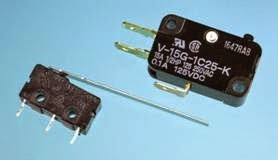
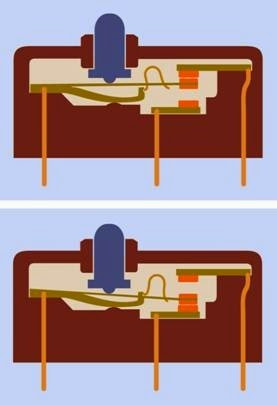
Two snap-action switches are shown in Figure 6-4. A sectional view of a snap-action ON- (ON) limit switch is shown in Figure 6-5. The pole contacts are mounted on a flexible strip which can move up and down in the center of the switch. The strip has a cutout which allows an inverted U-shaped spring to flip to and fro. It keeps the contacts pressed together in either of the switch states.


clip_image014

Figure 6-4. Two SPDT snap-action switches, also known as limit switches. The one on the right is full-size. The one on the left is miniature, with an actuator arm to provide additional leverage. The arm may be trimmed to the required length.

clip_image016

Figure 6-5. Top: Two contacts inside this limit switch are touching by default. Bottom: When the external button is pressed, it pushes a flexible metal strip downward until it connects with the lower contact. The inverted-U–shaped component is a spring that rests inside a cutout in the flexible strip and resists motion through the central part of its travel.

The term snap action refers to a spring-loaded internal mechanism which snaps to and fro be­ tween its two positions. This type of switch is usually SPDT and has a momentary action; in other words, it functions in ON-(ON) mode, al­ though OFF-(ON) and (less often) ON-(OFF) ver­sions are available. The body of the switch is sealed, with a small button protruding through a hole. A thin metal arm may provide additional leverage to press the button. A roller may be mounted at the end of the arm so that the switch can be activated as it slides against a moving mechanical component such as a cam or a wheel. The switch is commonly used to limit the travel or rotation of such a component. Literally thou­ sands of variants are available, in different sizes, requiring different amounts of force for activa­tion. Subminiature snap-action switches can often be actuated by a pressure of only a few grams.

Rocker

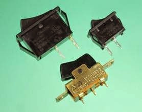
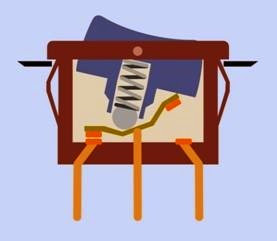
Three rocker switches are shown in Figure 6-6. A sectional view of a rocker switch is shown in Figure 6-7. In this design, a spring-loaded ball bearing rolls to either end of a central rocker arm when the switch is turned. Rocker switches are often used as power on-off switches.

Slider

Many types of slider switch (also known as slide switch) are widely used as a low-cost but versatile way to control small electronic devices, from clock-radios to stereos. The switch is usually mounted on a circuit board, and its knob or cap protrudes through a slot in the panel. This design is more vulnerable to dirt and moisture than oth­er types of switch. It is usually cheaper than a toggle switch but is seldom designed for use with a high current.

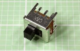
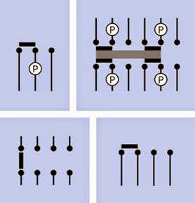
Most slide switches have two positions, and func­tion as SPDT or DPDT switches, but other config­urations are less commonly available with more poles and/or positions. A subminiature slide switch is shown in Figure 6-8, while some sche­matic representations are shown in Figure 6-9,

clip_image018

Figure 6-6. Three rocker switches, the upper two de- signed for push-insertion into a suitably sized rectangular hole in a panel. The switch at front-center is intended to be screwed in place, and is more than 20 years old, show- ing that while the choice of materials has changed, the ba- sic design has not.

clip_image020

Figure 6-7. This sectional view of a rocker switch shows a spring-loaded ball-bearing that rolls to and fro along a rocker arm, connecting either pair of contacts when the switch is turned.

where a black rectangle indicates a sliding inter­nal contact, and a terminal that functions as a pole is identified with letter P in each case. Top left: A SPDT switch using a two-position slider. Top right: A 4PDT slide switch. Bottom left: There are no poles in this switch, as such. The slider can

short together any of four pairs of contacts. Bot­ tom right: The slider shorts together three pos­sible pairs of contacts out of four. Here again, there is no pole.

Note that the schematic representation of a slide switch may be identical to that of a slide push­ button. A schematic should be inspected care­ fully to determine which type is intended.

clip_image022

Figure 6-8. This subminiature slide switch is less than half an inch long, rated 0.3A at 30VDC. Larger versions look almost identical, but can handle only slightly more current.

The representation of sliders in schematics has not been standardized, but the samples shown are common.

Toggle

A toggle switch provides a firm and precise action via a lever (the toggle) that is usually tear-drop shaped and nickel plated, although plastic tog­gles are common in cheaper variants. Formerly used to control almost all electronic components (including early computers), the toggle has de­clined in popularity but is still used in applica­tions such as automobile accessory kits, motor- boat instrument panels, and industrial controls.

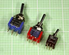
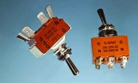
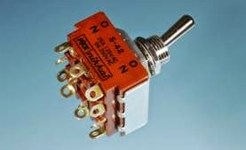
Three miniature DPDT toggle switches are shown in Figure 6-10. Two full-size, heavy-duty toggle switches are shown in Figure 6-11. A full-size, four-pole, double-throw heavy-duty toggle switch is shown in Figure 6-12. Toggle switches with more poles are extremely rare.


clip_image024

Figure 6-9. Slide switch schematics. Each black rectangle represents a movable contact that connects two pairs of fixed contacts at a time. Detailed commentary on these variants will be found in the body of the text. Manufacturers may use variants of these symbols in their datasheets (for example, the gray rectangle indicating an insulating contact carrier, at top right, may be represented as a single line, or a black outline with a white center).

clip_image026

Figure 6-10. Three miniature toggle switches with current ratings ranging from 0.3A to 6A at 125VAC. Each small square in the background grid measures 0.1” x 0.1”.

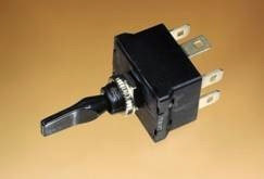
An automotive toggle switch is shown in Figure 6-13. Its plastic toggle is extended to min­imize operating error.

clip_image028

Figure 6-11. Two full-size toggle switches capable of handling significant current. At left, the switch terminates in quick-connect terminals. At right, the switch has solder terminals (some of them containing residual traces of sol- der).

clip_image030

Figure 6-12. A 4PDT full-size toggle switch with solder terminals, capable of switching 25A at 125VAC. Four-pole switches are relatively unusual.

clip_image032

Figure 6-13. A toggle switch intended for control of auto- motive accessories.

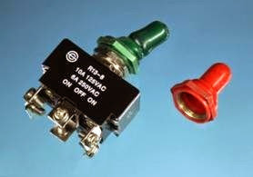
High-end toggle switches are extremely durable and can be sealed from environmental

contamination with a thin boot made from mol­ded rubber or vinyl, which screws in place over the toggle, using the thread on the switch bush­ing. See Figure 6-14.

clip_image034

Figure 6-14. A rubber or vinyl boot can be used to protect a toggle switch from contamination with dirt or water. Each boot contains a nut that screws onto the threads of a toggle switch, as shown at left.

A locking toggle switch has a toggle that must be pulled out against the force of a retaining spring, before the toggle can be moved from one posi­tion to another. The toggle then snaps back into place, usually engaging in a small slot in the bushing of the switch.

DIP

A DIP switch is an array of very small, separate switches, designed for mounting directly on a circuit board, either in through-hole or surface- mount format. Through-hole DIP switches have two rows of pins with a 0.1” pitch, the rows being spaced 0.3” apart to fit a standard DIP (dual-inline package) socket or comparable configuration of holes in the board. Surface-mount DIP switches may have 0.1” or 0.05” pitch.

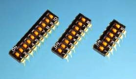
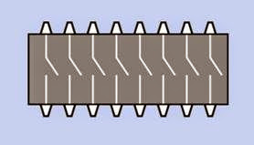
Most DIP arrays consist of SPST switches, each of which can close or open a connection between two pins on opposite sides of the switch body. The switch positions are usually labelled ON and OFF. Figure 6-15 shows a selection of DIP switches. Figure 6-16 shows the internal connec­tions in a DIP switch.

clip_image036

Figure 6-15. As shown here, DIP switches are available with a variety of “positions,” meaning the number of switches, not the number of switch states.

clip_image038

Figure 6-16. The interior connections of a 16-pin DIP switch.

The number of switches in a DIP array is usually referred to as its number of “positions.” This should not be confused with the two positions of each physical switch lever. SPST DIP switches are made with 1, 2, 3, 4, 5, 6, 7, 8, 9, 10, 12, and 16 positions.

Early IBM-compatible desktop computers often required the user to set the position of an internal DIP switch when making routine upgrades such as installing an additional disk drive. While this feature is now obsolete, DIP switches are still used in scientific equipment where the user is expected to be sufficiently competent to open a cabinet and poke around inside it. Because of the 0.1” spacing, a small screwdriver or the tip of a pen is more appropriate than a finger to flip in­dividual levers to and fro.

DIP switches may also be used during prototype development, as they allow a convenient way to test a circuit in numerous different modes of op­eration.

Most DIP switches have wire terminals which are just long enough for insertion into a standard breaboard.

DIP switch package options include standard, low-profile, right-angle (standing at 90 degrees relative to the circuit board), and piano (with switch levers designed to be pressed, like tiny rocker switches, instead of being flipped to and fro).

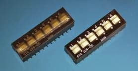
Some SPDT, DPST, DPDT, 3PST, and 4PST variants exist, but are uncommon. Multiple external pins connect with the additional internal switch con­tacts, and a manufacturer’s datasheet should be consulted to confirm the pattern of internal con­nections. A surface-mount, 0.1” pitch, DPST DIP switch is shown in Figure 6-17, with a plastic cov­er to protect the switches from contamination during wave soldering (at left), and with the cov­er peeled off (at right).

clip_image040

Figure 6-17. A SPDT surface-mount double-throw DIP switch, sold with a plastic cover (shown at left) to protect it during wave soldering. The cover has been removed at right.

SIP

A SIP switch is an array of small, separate switches, identical in concept to a DIP switch, but using only one row of pins instead of a double row. The applications for SIP switches are the

same as DIP switches; the primary difference is simply that the SIP switch occupies a little less space, while being perhaps slightly less conve­nient to use.

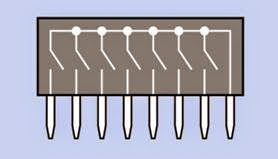
One terminal of each switch usually shares a common bus. The internal connections in a typ­ical 8-pin SIP array are shown in Figure 6-18. Pin spacing is 0.1”, as in a typical DIP switch.

clip_image042

Figure 6-18. The interior connections of an 8-pin SIP switch incorporating a common bus.

Paddle

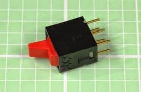
A paddle switch has a flat-sided tab-shaped plas­tic actuator, relatively large to allow a firm, error- free grip. Internally it is often comparable with a rocker switch, and is generally used with AC pow­er. Some toggle-switch bodies are also sold with paddle-shaped actuators. A subminiature pad­dle switch is shown in Figure 6-19.

clip_image044

Figure 6-19. A subminiature paddle switch. Full-size versions are often used as power switches.

Vandal Resistant Switch

Typically fabricated from stainless steel, this is designed to withstand most types of abuse and is also weather-proof. The pushbuttons that al­ low pedestrians to trigger a traffic signal are a form of vandal-resistant switch.

Tactile Switch

This is considered to be a pushbutton, and is described in that entry. See “Tactile Switch” (page 34).

Mounting Options

A panel mount switch generally has a threaded bushing that is inserted from behind the front panel of a product, through a hole of appropriate size. It is supplied with a lock washer and a nut (often, two nuts) that fit the thread on the switch bushing.

Front panel mount usually means that screws visi­ble from the front of the panel are attached to a bracket on the switch behind the panel. The ac­tuator of the switch is accessible through a cut­ out in the panel. This mounting style is mostly used for rocker switches and sometimes for slide switches.

Subpanel mount means that the switch is attach­ ed to a separate plate or chassis behind the con­trol panel. The actuator of the switch is accessible through a cutout.

Snap-in mount requires a switch with flexible plastic or metal tabs each side, designed to push through a cutout in the panel, at which point the tabs spring out and retain the switch.

PC mount switches have pins that are soldered into a printed circuit board. They may have ad­ditional solderable lugs to provide mechanical support.

Surface mount switches are attached to a board in the same manner as other surface-mount components.


Termination

Switches (and pushbuttons) are available with a variety of terminals.

Solder lugs are small tabs, each usually perforated with a hole through which the end of a wire can be inserted prior to soldering.

PC terminals are pins that protrude from the bot­ tom of the switch, suitable for insertion in a print­ ed circuit board. This style is also known as a through-hole. The terminals may have a right- angle bend to allow the component to be moun­ ted flat against the board, with the switch actua­ tor sticking out at the side. This termination style is known as right-angle PC. Many manufacturers offer a choice of straight or bent pin terminals, but the component may be listed in a catalog under either of those options, with no indication that other options exist. Check manufacturer da­ tasheets carefully.

Quick connect terminals are spade-shaped to ac­cept push-on connectors, commonly used in au­ tomotive applications. Hybrid quick-connect ter­minals that can also function as solder lugs are sometimes offered as an option.

Screw terminals have screws premounted in flat terminals, for solderless attachment of wires.

Wire leads are flexible insulated wires, often with stripped and tinned ends, protruding at least an inch from the body of the component. This op­tion is becoming uncommon.

Contact Plating Options

The internal electrical contacts of a switch are usually plated with silver or gold. Nickel, tin, and silver alloys are cheaper but less common. Other types are relatively rare.

alues

Switches designed for electronic devices vary widely in power capability, depending on their purpose. Rocker switches, paddle switches, and toggle switches are often used to turn power on and off, and are typically rated for 10A at 125VAC,

although some toggle switches go as high as 30A. Snap-action or limit switches may be simi­larly rated, although miniature versions will have reduced capability. Slide switches cannot handle significant power, and are often rated around 0.5A (or less) at 30VDC. DIP and SIP switches have a typical maximum rating of 100mA at 50V and are not designed for frequent use. Generally they are used only when the power to the device is off.

How to Use it
Power Switches

When a simple SPST switch is used to turn DC power on and off, it conventionally switches the positive side of the power supply, also some­ times known as the high side. The primary reason for following this convention is that it is widely used; thus, following it will reduce confusion.

More importantly, an on-off switch that controls AC power must be used on the “live” side of the supply, not the “neutral” side. If you have any doubts about these concepts (which go beyond the scope of this book), consult a reference guide on this subject. Using a DPST component to switch both sides of an AC supply may be a worthwhile additional precaution in some applications. The ground wire of an AC supply should never be switched, because the device should always be grounded when it is plugged into an electric outlet.

Limit Switches

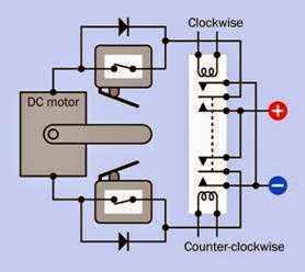
An application for two limit switches with a DC motor and two rectifier diodes is shown in Figure 6-20. This diagram assumes that the mo­ tor turns clockwise when its lower terminal is positive, and counter-clockwise when its upper terminal is positive. Only two terminals are used (and shown) in each limit switch; they are chosen to be normally-closed. Other terminals inside a switch may exist, may be normally-open, and can be ignored.

The motor is driven through a dual-coil, DPDT latching relay, which will remain in either posi­

clip_image047

Figure 6-20. In this schematic, normally-closed limit switches are opened by pressure from an arm attached to a motor, thus switching off its power at each end of its permitted travel and preventing overload and burnout. A two-coil latching relay activates the motor. Rectifier di- odes allow power to reach the motor to reverse its rota- tion when a limit switch is open.

tion indefinitely without drawing power. When the upper coil of the relay receives a pulse from a pushbutton or some other source, the relay flips to its upper position, which conducts posi­ tive current through the lower limit switch, to the lower terminal of the motor. The motor turns clockwise until the arm attached to its shaft hits the lower limit switch and opens it. Positive cur­ rent is blocked by the lower diode, so the motor stops.

When the lower coil of the relay is activated, the relay flips to its lower position. Positive current can now reach the upper side of the motor through the upper limit switch. The motor runs counter-clockwise until its arm opens the upper limit switch, at which point the motor stops again. This simple system allows a DC motor to be run in either direction by a button-press of any duration, without risk of burnout when the mo­ tor reaches the end of its travel. It has been used for applications such as raising and lowering powered windows in an automobile.


A DPDT pushbutton could be substituted for the latching relay if manual control, only, is accepta­ble. However, in this scenario, sustained pressure on the pushbutton would be necessary to move the motor arm all the way to the opposite end of its travel. A DPDT switch might be more appro­priate than a pushbutton.

Logic Circuits

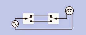
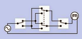
Logic circuits that depend purely on switches can be constructed (for example, to add binary num­bers) but are rare and have no practical applica­tions. The most familiar and simplest example of manually switched logic is a pair of SPDT switches in house wiring, one positioned at the top of a flight of stairs and the other at the bot­ tom, as shown in Figure 6-21. Either switch will turn the light on if it is currently off, or off if it is currently on. To extend this circuit by incorpo­rating a third switch that has the same function as the other two, a DPDT switch must be inserted. See Figure 6-22.

clip_image049

Figure 6-21. SPDT switches are commonly used in house wiring so that either of them will turn a shared light on if it is off, or off it is on.

clip_image051

Figure 6-22. A DPDT switch must be inserted if three switches must have identical function to control the on-off state of a single light bulb.


Alternatives

As microcontrollers have become cheaper and more ubiquitous, they have taken over many functions in electronic products that used to be served by switches. A menuing system driven by a microcontroller can use one rotational en­ coder with a SPST pushbutton built into it to se­lect and adjust numerous parameters in a device such as a car stereo, where functions were once selected and adjusted by individual switches and potentiometers. The rotational-encoder option takes up less space, is cheaper to build (assuming a microcontroller is going to be used in the de­ vice for other purposes anyway), and can be more reliable, as it reduces the number of elec­tromechanical parts. Whether it is easier to use is a matter of taste. Cost and ergonomics may be the primary factors to consider when choosing where and how to use switches.

What Can Go Wrong
Arcing

The contacts inside a switch will be rapidly ero­ded if arcing (pronounced “arking”) occurs. An electric arc is a spark that tends to form when a switch is opened while conducting a high cur­ rent or high voltage (typically 10A or more and 100V or more). The most common cause is an inductive load that generates back-EMF when it is switched on and forward-EMF when it is switched off. The surge can be many times the amperage that the load draws during continu­ous operation. In DC circuits, arcing can be re­duced by using a rectifier diode in parallel with the load (with its polarity blocking normal cur­ rent flow). This is often referred to as a flyback diode or freewheeling diode. In AC circuits, where a diode cannot be used in this way, a snubber (a simple combination of capacitor and resistor) may be placed around the load. A snubber can also be used around the switch itself, in DC cir­cuits. See “Snubber” (page 108).

When switching an inductive load, it is generally prudent to use switches rated for twice as much current as the circuit will normally draw.

Dry Joints

Switches that control significant current will have substantial terminals, and these terminals will be attached to heavy-gauge wire. When using sol­ der to make this type of connection, the combined heat capacity of the wire and the terminal will sink a lot more heat than a small component on a circuit board. At least a 30W soldering iron should be used. Lower-wattage irons may be in­ capable of melting the solder completely (even though they seem to), and a “dry joint” will result, which can have a relatively high electrical resist­ance and will be mechanically weak, liable to break later. Any good solder joint should with­ stand flexing of the wire attached to it.

Short Circuits

Because many switches are still wired in with sol­ der tabs, screw terminals, or quick-connect ter­minals, wires that become accidentally detached can be a significant hazard. Heat-shrink tubing should be applied to enclose wires and terminals at the rear of a power switch, as an additional precaution. Power switches should always be used in conjunction with appropriate fuses.

Contact Contamination

Sealed switches should be used in any environ­ment where dirt or water may be present. Slide switches are especially vulnerable to contamina­tion, and are difficult to seal. Switches used in audio components will create “scratchy” sounds if their contacts deteriorate.

Wrong Terminal Type

Because switches are available with a wide vari­ety of terminal types, it’s easy to order the wrong type. Switches may be supplied with pins for through-hole insertion in circuit boards; screw terminals; quick-disconnect terminals; or solder lugs. Variants may also be available for surface

mount. If a project requires, for example, the in­ sertion of pins in a printed circuit board, and a switch is supplied with solder lugs, it will be un­ usable.

Part numbers generally include codes to identify each terminal variant, and should be studied carefully.

Contact Bounce

Also known as switch bounce. When two contacts snap together, extremely rapid, microscopic vi­brations occur that cause brief interruptions be­ fore the contacts settle. While this phenomenon is not perceptible to human senses, it can be per­ ceived as a series of multiple pulses by a logic chip. For this reason, various strategies are used to debounce a switch that drives a logic input. This issue is explored in detail in the entry on logic chips in Volume 2 of the encyclopedia.

Mechanical Wear

Any toggle or rocker switch contains a mechan­ical pivot, which tend to deteriorate in harsh en­vironments. Friction is also an issue inside these switches, as the design often entails the rounded tip of a lever rubbing to and fro across the center of a movable contact.

The spring inside a snap switch or limit switch may fail as a result of metal fatigue, although this is rare. A slide switch is far less durable, as its con­tacts rub across each other every time the switch changes position.

In any application that entails frequent switch­ing, or where switch failure is a critical issue, the most sensible practice is to avoid using cheap switches.

Mounting Problems

In a panel-mount switch that is secured by turn­ ing a nut, the nut may loosen with use, allowing the component to fall inside its enclosure. Con­ versely, overtightening the nut may strip the threads on the switch body, especially in cheaper components where the threads are molded into

plastic. Consider applying a drop of Loc-Tite or similar adhesive after moderately tightening the nut. Note that nut sizes vary widely, and finding a replacement may be time-consuming.

Cryptic Schematics

In some circuit schematics, the poles of a multi- pole switch may be visually separated from each

other, even at opposite sides of the page, for convenience in drawing the schematic. Dotted lines usually, but not always, link the poles. In the absence of dotted lines, switch segments are often coded to indicate their commonality. For example, SW1(a) and SW1(b) are almost certainly different parts of the same switch, with linked poles.

Leave a comment

Your email address will not be published. Required fields are marked *

switch What It Does,How It Works ,Variants,Values,How to Use it and What Can Go Wrong


The term switch refers here to a physically operated mechanical switch, controlled by flipping a lever or sliding a knob. Although there is some overlap of function, rotary switches and pushbuttons have their own separate entries. Solid-state switching com­ponents are described in entries for bipolar transistor, unijunction transistor, and field-effect transistor. Integrated-circuit switching devices will be found in Volume 2. Coaxial switches are used for high-frequency signals, and are not included in this ency­clopedia. Multidirectional switches differentiate up, down, left, right, diagonal, rotational, and other finger inputs, and are not included in this encyclopedia.

What It Does

A switch contains at least two contacts, which close or open when an external lever or knob is flipped or moved. Schematic symbols for the most basic type of on-off switch are shown in Figure 6-1.

The most fundamental type of switch is a knife switch, illustrated in Figure 6-2. Although it was common in the earliest days of electrical discov­ery, today it is restricted to educational purposes in schools, and (in a more robust format) to AC electrical supply panels, where the large contact area makes it appropriate for conducting high amperages, and it can be used for “hot switching” a substantial load.

How It Works

The pole of a switch is generally connected with a movable contact that makes or breaks a con­nection with a secondary contact. If there is only one pole, this is a single-pole switch. If there is an additional pole, electrically isolated from the

clip_image004

Figure 6-1. The two most common schematic symbols for a SPST switch, also known as an on-off switch. The symbols are functionally identical.

first, with its own contact or set of contacts, this is a two-pole switch, also known as a double- pole switch. Switches with more than 4 poles are uncommon.

If there is only one secondary contact per pole, this is a single-throw or ST switch, which may also be described as an on-off or off-on switch. If there is an additional secondary contact per pole, and the pole of the switch connects with the second contact while disconnecting from the first, this is a double-throw or DT switch, also known as a two– way switch.

clip_image007

Figure 6-2. A DPST knife switch intended for the educational environment.

A double-throw switch may have an additional center position. This position may have no con­nection (it is an “off” position) or in some cases it connects with a third contact.

Where a switch is spring-loaded to return to one of its positions when manual pressure is released, it functions like a pushbutton even though its physical appearance may be indistinguishable from a switch.

Variants

Float switch, mercury switch, reed switch, pressure switch, and Hall-effect switch are considered as sensing devices, and will be found in Volume 3.

Terminology

Many different types of switches contain parts that serve the same common functions. The ac­tuator is the lever, knob, or toggle that the user turns or pushes. A bushing surrounds the actua­ tor on a toggle-type switch. The common con­ tact inside a switch is connected with the pole of

the switch. Usually a movable contact is attached to it internally, to touch the secondary contact, also known as a stationary contact when the movable contact is flipped to and fro.

Poles and Throws

Abbreviations identify the number of poles and contacts inside a switch. A few examples will make this clear:

SPST also known as 1P1T

Single pole, single throw

DPST also known as 2P1T

Double pole, single throw

SPDT also known as 1P2T

Single pole, double throw

3PST also known as 3P1T

Three pole, single throw

Other combinations are possible.

In Figure 6-3, schematic symbols are shown for double-throw switches with 1, 2, and 3 poles. The dashed lines indicate a mechanical connection, so that all sections of the switch move together when the switch is turned. No electrical connec­tion exists between the poles.

clip_image010

Figure 6-3. Schematic symbols to represent three types of double-throw switch. Top left: Single-pole. Bottom left: Double-pole. Right: Triple-pole, more commonly known as 3-pole.

On-Off Behavior

The words ON and OFF are used to indicate the possible states of a switch. The additional word NONE is used by some manufacturers to indicate that a switch does not have a center position. Some manufacturers don’t bother with the word NONE, assuming that if the word is omitted, a center position does not exist.

ON-OFF or ON-NONE-OFF

A basic on-off SPST switch with no center position.

ON-ON or ON-NONE-ON

A basic SPDT switch with no center position.

ON-OFF-ON

A double-throw switch with center-off posi­tion (no connection when the switch is cen­tered).

ON-ON-ON

A triple-throw switch where the center po­sition connects with its own set of terminals.

Parentheses are used in descriptions of spring- loaded switches to indicate a momentary state that lasts only as long as pressure is applied to the actuator.

(ON)-OFF or OFF-(ON)

A spring-loaded switch that is normally off and returns to that position when pressure is released. Also known as NO (normally open), and sometimes described as FORM A. Its performance is similar to that of a push­ button and is sometimes described as a make-to-make connection.

ON-(OFF) or (OFF)-ON

A spring-loaded switch that is normally on and returns to that position when pressure is released. This is sometimes described as a make-to-break connection. Also known as NC (normally closed), and sometimes de­ scribed as FORM B.

(ON)-OFF-(ON)

A spring-loaded double-throw switch with a no-connection center position to which it returns when pressure on its actuator is re­ leased.

Other combinations of these terms are possible. Most double-throw switches break the connec­tion with one contact (or set of contacts) before making the connection with the second contact (or set of contacts). This is known as a break before make switch. Much less common is a make before break switch, also known as a shorting switch, which establishes the second connection a mo­ment before the first connection is broken. Use of a shorting switch may cause unforeseen con­ sequences in electronic components attached to it, as both sides of the switch will be briefly con­nected when the switch is turned.

Snap-Action

Also known as a limit switch and sometimes as a micros witch or basic switch. This utilitarian design is often intended to be triggered mechanically rather than with finger pressure, for example in 3D printers. It is generally cheap but reliable.

Two snap-action switches are shown in Figure 6-4. A sectional view of a snap-action ON- (ON) limit switch is shown in Figure 6-5. The pole contacts are mounted on a flexible strip which can move up and down in the center of the switch. The strip has a cutout which allows an inverted U-shaped spring to flip to and fro. It keeps the contacts pressed together in either of the switch states.


clip_image014

Figure 6-4. Two SPDT snap-action switches, also known as limit switches. The one on the right is full-size. The one on the left is miniature, with an actuator arm to provide additional leverage. The arm may be trimmed to the required length.

clip_image016

Figure 6-5. Top: Two contacts inside this limit switch are touching by default. Bottom: When the external button is pressed, it pushes a flexible metal strip downward until it connects with the lower contact. The inverted-U–shaped component is a spring that rests inside a cutout in the flexible strip and resists motion through the central part of its travel.

The term snap action refers to a spring-loaded internal mechanism which snaps to and fro be­ tween its two positions. This type of switch is usually SPDT and has a momentary action; in other words, it functions in ON-(ON) mode, al­ though OFF-(ON) and (less often) ON-(OFF) ver­sions are available. The body of the switch is sealed, with a small button protruding through a hole. A thin metal arm may provide additional leverage to press the button. A roller may be mounted at the end of the arm so that the switch can be activated as it slides against a moving mechanical component such as a cam or a wheel. The switch is commonly used to limit the travel or rotation of such a component. Literally thou­ sands of variants are available, in different sizes, requiring different amounts of force for activa­tion. Subminiature snap-action switches can often be actuated by a pressure of only a few grams.

Rocker

Three rocker switches are shown in Figure 6-6. A sectional view of a rocker switch is shown in Figure 6-7. In this design, a spring-loaded ball bearing rolls to either end of a central rocker arm when the switch is turned. Rocker switches are often used as power on-off switches.

Slider

Many types of slider switch (also known as slide switch) are widely used as a low-cost but versatile way to control small electronic devices, from clock-radios to stereos. The switch is usually mounted on a circuit board, and its knob or cap protrudes through a slot in the panel. This design is more vulnerable to dirt and moisture than oth­er types of switch. It is usually cheaper than a toggle switch but is seldom designed for use with a high current.

Most slide switches have two positions, and func­tion as SPDT or DPDT switches, but other config­urations are less commonly available with more poles and/or positions. A subminiature slide switch is shown in Figure 6-8, while some sche­matic representations are shown in Figure 6-9,

clip_image018

Figure 6-6. Three rocker switches, the upper two de- signed for push-insertion into a suitably sized rectangular hole in a panel. The switch at front-center is intended to be screwed in place, and is more than 20 years old, show- ing that while the choice of materials has changed, the ba- sic design has not.

clip_image020

Figure 6-7. This sectional view of a rocker switch shows a spring-loaded ball-bearing that rolls to and fro along a rocker arm, connecting either pair of contacts when the switch is turned.

where a black rectangle indicates a sliding inter­nal contact, and a terminal that functions as a pole is identified with letter P in each case. Top left: A SPDT switch using a two-position slider. Top right: A 4PDT slide switch. Bottom left: There are no poles in this switch, as such. The slider can

short together any of four pairs of contacts. Bot­ tom right: The slider shorts together three pos­sible pairs of contacts out of four. Here again, there is no pole.

Note that the schematic representation of a slide switch may be identical to that of a slide push­ button. A schematic should be inspected care­ fully to determine which type is intended.

clip_image022

Figure 6-8. This subminiature slide switch is less than half an inch long, rated 0.3A at 30VDC. Larger versions look almost identical, but can handle only slightly more current.

The representation of sliders in schematics has not been standardized, but the samples shown are common.

Toggle

A toggle switch provides a firm and precise action via a lever (the toggle) that is usually tear-drop shaped and nickel plated, although plastic tog­gles are common in cheaper variants. Formerly used to control almost all electronic components (including early computers), the toggle has de­clined in popularity but is still used in applica­tions such as automobile accessory kits, motor- boat instrument panels, and industrial controls.

Three miniature DPDT toggle switches are shown in Figure 6-10. Two full-size, heavy-duty toggle switches are shown in Figure 6-11. A full-size, four-pole, double-throw heavy-duty toggle switch is shown in Figure 6-12. Toggle switches with more poles are extremely rare.


clip_image024

Figure 6-9. Slide switch schematics. Each black rectangle represents a movable contact that connects two pairs of fixed contacts at a time. Detailed commentary on these variants will be found in the body of the text. Manufacturers may use variants of these symbols in their datasheets (for example, the gray rectangle indicating an insulating contact carrier, at top right, may be represented as a single line, or a black outline with a white center).

clip_image026

Figure 6-10. Three miniature toggle switches with current ratings ranging from 0.3A to 6A at 125VAC. Each small square in the background grid measures 0.1” x 0.1”.

An automotive toggle switch is shown in Figure 6-13. Its plastic toggle is extended to min­imize operating error.

clip_image028

Figure 6-11. Two full-size toggle switches capable of handling significant current. At left, the switch terminates in quick-connect terminals. At right, the switch has solder terminals (some of them containing residual traces of sol- der).

clip_image030

Figure 6-12. A 4PDT full-size toggle switch with solder terminals, capable of switching 25A at 125VAC. Four-pole switches are relatively unusual.

clip_image032

Figure 6-13. A toggle switch intended for control of auto- motive accessories.

High-end toggle switches are extremely durable and can be sealed from environmental

contamination with a thin boot made from mol­ded rubber or vinyl, which screws in place over the toggle, using the thread on the switch bush­ing. See Figure 6-14.

clip_image034

Figure 6-14. A rubber or vinyl boot can be used to protect a toggle switch from contamination with dirt or water. Each boot contains a nut that screws onto the threads of a toggle switch, as shown at left.

A locking toggle switch has a toggle that must be pulled out against the force of a retaining spring, before the toggle can be moved from one posi­tion to another. The toggle then snaps back into place, usually engaging in a small slot in the bushing of the switch.

DIP

A DIP switch is an array of very small, separate switches, designed for mounting directly on a circuit board, either in through-hole or surface- mount format. Through-hole DIP switches have two rows of pins with a 0.1” pitch, the rows being spaced 0.3” apart to fit a standard DIP (dual-inline package) socket or comparable configuration of holes in the board. Surface-mount DIP switches may have 0.1” or 0.05” pitch.

Most DIP arrays consist of SPST switches, each of which can close or open a connection between two pins on opposite sides of the switch body. The switch positions are usually labelled ON and OFF. Figure 6-15 shows a selection of DIP switches. Figure 6-16 shows the internal connec­tions in a DIP switch.

clip_image036

Figure 6-15. As shown here, DIP switches are available with a variety of “positions,” meaning the number of switches, not the number of switch states.

clip_image038

Figure 6-16. The interior connections of a 16-pin DIP switch.

The number of switches in a DIP array is usually referred to as its number of “positions.” This should not be confused with the two positions of each physical switch lever. SPST DIP switches are made with 1, 2, 3, 4, 5, 6, 7, 8, 9, 10, 12, and 16 positions.

Early IBM-compatible desktop computers often required the user to set the position of an internal DIP switch when making routine upgrades such as installing an additional disk drive. While this feature is now obsolete, DIP switches are still used in scientific equipment where the user is expected to be sufficiently competent to open a cabinet and poke around inside it. Because of the 0.1” spacing, a small screwdriver or the tip of a pen is more appropriate than a finger to flip in­dividual levers to and fro.

DIP switches may also be used during prototype development, as they allow a convenient way to test a circuit in numerous different modes of op­eration.

Most DIP switches have wire terminals which are just long enough for insertion into a standard breaboard.

DIP switch package options include standard, low-profile, right-angle (standing at 90 degrees relative to the circuit board), and piano (with switch levers designed to be pressed, like tiny rocker switches, instead of being flipped to and fro).

Some SPDT, DPST, DPDT, 3PST, and 4PST variants exist, but are uncommon. Multiple external pins connect with the additional internal switch con­tacts, and a manufacturer’s datasheet should be consulted to confirm the pattern of internal con­nections. A surface-mount, 0.1” pitch, DPST DIP switch is shown in Figure 6-17, with a plastic cov­er to protect the switches from contamination during wave soldering (at left), and with the cov­er peeled off (at right).

clip_image040

Figure 6-17. A SPDT surface-mount double-throw DIP switch, sold with a plastic cover (shown at left) to protect it during wave soldering. The cover has been removed at right.

SIP

A SIP switch is an array of small, separate switches, identical in concept to a DIP switch, but using only one row of pins instead of a double row. The applications for SIP switches are the

same as DIP switches; the primary difference is simply that the SIP switch occupies a little less space, while being perhaps slightly less conve­nient to use.

One terminal of each switch usually shares a common bus. The internal connections in a typ­ical 8-pin SIP array are shown in Figure 6-18. Pin spacing is 0.1”, as in a typical DIP switch.

clip_image042

Figure 6-18. The interior connections of an 8-pin SIP switch incorporating a common bus.

Paddle

A paddle switch has a flat-sided tab-shaped plas­tic actuator, relatively large to allow a firm, error- free grip. Internally it is often comparable with a rocker switch, and is generally used with AC pow­er. Some toggle-switch bodies are also sold with paddle-shaped actuators. A subminiature pad­dle switch is shown in Figure 6-19.

clip_image044

Figure 6-19. A subminiature paddle switch. Full-size versions are often used as power switches.

Vandal Resistant Switch

Typically fabricated from stainless steel, this is designed to withstand most types of abuse and is also weather-proof. The pushbuttons that al­ low pedestrians to trigger a traffic signal are a form of vandal-resistant switch.

Tactile Switch

This is considered to be a pushbutton, and is described in that entry. See “Tactile Switch” (page 34).

Mounting Options

A panel mount switch generally has a threaded bushing that is inserted from behind the front panel of a product, through a hole of appropriate size. It is supplied with a lock washer and a nut (often, two nuts) that fit the thread on the switch bushing.

Front panel mount usually means that screws visi­ble from the front of the panel are attached to a bracket on the switch behind the panel. The ac­tuator of the switch is accessible through a cut­ out in the panel. This mounting style is mostly used for rocker switches and sometimes for slide switches.

Subpanel mount means that the switch is attach­ ed to a separate plate or chassis behind the con­trol panel. The actuator of the switch is accessible through a cutout.

Snap-in mount requires a switch with flexible plastic or metal tabs each side, designed to push through a cutout in the panel, at which point the tabs spring out and retain the switch.

PC mount switches have pins that are soldered into a printed circuit board. They may have ad­ditional solderable lugs to provide mechanical support.

Surface mount switches are attached to a board in the same manner as other surface-mount components.


Termination

Switches (and pushbuttons) are available with a variety of terminals.

Solder lugs are small tabs, each usually perforated with a hole through which the end of a wire can be inserted prior to soldering.

PC terminals are pins that protrude from the bot­ tom of the switch, suitable for insertion in a print­ ed circuit board. This style is also known as a through-hole. The terminals may have a right- angle bend to allow the component to be moun­ ted flat against the board, with the switch actua­ tor sticking out at the side. This termination style is known as right-angle PC. Many manufacturers offer a choice of straight or bent pin terminals, but the component may be listed in a catalog under either of those options, with no indication that other options exist. Check manufacturer da­ tasheets carefully.

Quick connect terminals are spade-shaped to ac­cept push-on connectors, commonly used in au­ tomotive applications. Hybrid quick-connect ter­minals that can also function as solder lugs are sometimes offered as an option.

Screw terminals have screws premounted in flat terminals, for solderless attachment of wires.

Wire leads are flexible insulated wires, often with stripped and tinned ends, protruding at least an inch from the body of the component. This op­tion is becoming uncommon.

Contact Plating Options

The internal electrical contacts of a switch are usually plated with silver or gold. Nickel, tin, and silver alloys are cheaper but less common. Other types are relatively rare.

alues

Switches designed for electronic devices vary widely in power capability, depending on their purpose. Rocker switches, paddle switches, and toggle switches are often used to turn power on and off, and are typically rated for 10A at 125VAC,

although some toggle switches go as high as 30A. Snap-action or limit switches may be simi­larly rated, although miniature versions will have reduced capability. Slide switches cannot handle significant power, and are often rated around 0.5A (or less) at 30VDC. DIP and SIP switches have a typical maximum rating of 100mA at 50V and are not designed for frequent use. Generally they are used only when the power to the device is off.

How to Use it
Power Switches

When a simple SPST switch is used to turn DC power on and off, it conventionally switches the positive side of the power supply, also some­ times known as the high side. The primary reason for following this convention is that it is widely used; thus, following it will reduce confusion.

More importantly, an on-off switch that controls AC power must be used on the “live” side of the supply, not the “neutral” side. If you have any doubts about these concepts (which go beyond the scope of this book), consult a reference guide on this subject. Using a DPST component to switch both sides of an AC supply may be a worthwhile additional precaution in some applications. The ground wire of an AC supply should never be switched, because the device should always be grounded when it is plugged into an electric outlet.

Limit Switches

An application for two limit switches with a DC motor and two rectifier diodes is shown in Figure 6-20. This diagram assumes that the mo­ tor turns clockwise when its lower terminal is positive, and counter-clockwise when its upper terminal is positive. Only two terminals are used (and shown) in each limit switch; they are chosen to be normally-closed. Other terminals inside a switch may exist, may be normally-open, and can be ignored.

The motor is driven through a dual-coil, DPDT latching relay, which will remain in either posi­

clip_image047

Figure 6-20. In this schematic, normally-closed limit switches are opened by pressure from an arm attached to a motor, thus switching off its power at each end of its permitted travel and preventing overload and burnout. A two-coil latching relay activates the motor. Rectifier di- odes allow power to reach the motor to reverse its rota- tion when a limit switch is open.

tion indefinitely without drawing power. When the upper coil of the relay receives a pulse from a pushbutton or some other source, the relay flips to its upper position, which conducts posi­ tive current through the lower limit switch, to the lower terminal of the motor. The motor turns clockwise until the arm attached to its shaft hits the lower limit switch and opens it. Positive cur­ rent is blocked by the lower diode, so the motor stops.

When the lower coil of the relay is activated, the relay flips to its lower position. Positive current can now reach the upper side of the motor through the upper limit switch. The motor runs counter-clockwise until its arm opens the upper limit switch, at which point the motor stops again. This simple system allows a DC motor to be run in either direction by a button-press of any duration, without risk of burnout when the mo­ tor reaches the end of its travel. It has been used for applications such as raising and lowering powered windows in an automobile.


A DPDT pushbutton could be substituted for the latching relay if manual control, only, is accepta­ble. However, in this scenario, sustained pressure on the pushbutton would be necessary to move the motor arm all the way to the opposite end of its travel. A DPDT switch might be more appro­priate than a pushbutton.

Logic Circuits

Logic circuits that depend purely on switches can be constructed (for example, to add binary num­bers) but are rare and have no practical applica­tions. The most familiar and simplest example of manually switched logic is a pair of SPDT switches in house wiring, one positioned at the top of a flight of stairs and the other at the bot­ tom, as shown in Figure 6-21. Either switch will turn the light on if it is currently off, or off if it is currently on. To extend this circuit by incorpo­rating a third switch that has the same function as the other two, a DPDT switch must be inserted. See Figure 6-22.

clip_image049

Figure 6-21. SPDT switches are commonly used in house wiring so that either of them will turn a shared light on if it is off, or off it is on.

clip_image051

Figure 6-22. A DPDT switch must be inserted if three switches must have identical function to control the on-off state of a single light bulb.


Alternatives

As microcontrollers have become cheaper and more ubiquitous, they have taken over many functions in electronic products that used to be served by switches. A menuing system driven by a microcontroller can use one rotational en­ coder with a SPST pushbutton built into it to se­lect and adjust numerous parameters in a device such as a car stereo, where functions were once selected and adjusted by individual switches and potentiometers. The rotational-encoder option takes up less space, is cheaper to build (assuming a microcontroller is going to be used in the de­ vice for other purposes anyway), and can be more reliable, as it reduces the number of elec­tromechanical parts. Whether it is easier to use is a matter of taste. Cost and ergonomics may be the primary factors to consider when choosing where and how to use switches.

What Can Go Wrong
Arcing

The contacts inside a switch will be rapidly ero­ded if arcing (pronounced “arking”) occurs. An electric arc is a spark that tends to form when a switch is opened while conducting a high cur­ rent or high voltage (typically 10A or more and 100V or more). The most common cause is an inductive load that generates back-EMF when it is switched on and forward-EMF when it is switched off. The surge can be many times the amperage that the load draws during continu­ous operation. In DC circuits, arcing can be re­duced by using a rectifier diode in parallel with the load (with its polarity blocking normal cur­ rent flow). This is often referred to as a flyback diode or freewheeling diode. In AC circuits, where a diode cannot be used in this way, a snubber (a simple combination of capacitor and resistor) may be placed around the load. A snubber can also be used around the switch itself, in DC cir­cuits. See “Snubber” (page 108).

When switching an inductive load, it is generally prudent to use switches rated for twice as much current as the circuit will normally draw.

Dry Joints

Switches that control significant current will have substantial terminals, and these terminals will be attached to heavy-gauge wire. When using sol­ der to make this type of connection, the combined heat capacity of the wire and the terminal will sink a lot more heat than a small component on a circuit board. At least a 30W soldering iron should be used. Lower-wattage irons may be in­ capable of melting the solder completely (even though they seem to), and a “dry joint” will result, which can have a relatively high electrical resist­ance and will be mechanically weak, liable to break later. Any good solder joint should with­ stand flexing of the wire attached to it.

Short Circuits

Because many switches are still wired in with sol­ der tabs, screw terminals, or quick-connect ter­minals, wires that become accidentally detached can be a significant hazard. Heat-shrink tubing should be applied to enclose wires and terminals at the rear of a power switch, as an additional precaution. Power switches should always be used in conjunction with appropriate fuses.

Contact Contamination

Sealed switches should be used in any environ­ment where dirt or water may be present. Slide switches are especially vulnerable to contamina­tion, and are difficult to seal. Switches used in audio components will create “scratchy” sounds if their contacts deteriorate.

Wrong Terminal Type

Because switches are available with a wide vari­ety of terminal types, it’s easy to order the wrong type. Switches may be supplied with pins for through-hole insertion in circuit boards; screw terminals; quick-disconnect terminals; or solder lugs. Variants may also be available for surface

mount. If a project requires, for example, the in­ sertion of pins in a printed circuit board, and a switch is supplied with solder lugs, it will be un­ usable.

Part numbers generally include codes to identify each terminal variant, and should be studied carefully.

Contact Bounce

Also known as switch bounce. When two contacts snap together, extremely rapid, microscopic vi­brations occur that cause brief interruptions be­ fore the contacts settle. While this phenomenon is not perceptible to human senses, it can be per­ ceived as a series of multiple pulses by a logic chip. For this reason, various strategies are used to debounce a switch that drives a logic input. This issue is explored in detail in the entry on logic chips in Volume 2 of the encyclopedia.

Mechanical Wear

Any toggle or rocker switch contains a mechan­ical pivot, which tend to deteriorate in harsh en­vironments. Friction is also an issue inside these switches, as the design often entails the rounded tip of a lever rubbing to and fro across the center of a movable contact.

The spring inside a snap switch or limit switch may fail as a result of metal fatigue, although this is rare. A slide switch is far less durable, as its con­tacts rub across each other every time the switch changes position.

In any application that entails frequent switch­ing, or where switch failure is a critical issue, the most sensible practice is to avoid using cheap switches.

Mounting Problems

In a panel-mount switch that is secured by turn­ ing a nut, the nut may loosen with use, allowing the component to fall inside its enclosure. Con­ versely, overtightening the nut may strip the threads on the switch body, especially in cheaper components where the threads are molded into

plastic. Consider applying a drop of Loc-Tite or similar adhesive after moderately tightening the nut. Note that nut sizes vary widely, and finding a replacement may be time-consuming.

Cryptic Schematics

In some circuit schematics, the poles of a multi- pole switch may be visually separated from each

other, even at opposite sides of the page, for convenience in drawing the schematic. Dotted lines usually, but not always, link the poles. In the absence of dotted lines, switch segments are often coded to indicate their commonality. For example, SW1(a) and SW1(b) are almost certainly different parts of the same switch, with linked poles.
Leave a comment

Your email address will not be published. Required fields are marked *