The term inductor is used here to describe a coil that has the purpose of creating self- inductance in an electronic circuit, often while passing alternating current in combination with resistors and/or capacitors. A choke is a form of inductor. By comparison, the electromagnet entry in this encyclopedia describes a coil containing a center component of ferromagnetic material that does not move relative to the coil, and has the purpose of attracting or repelling other parts that respond to a magnetic field. A coil containing a center component of ferromagnetic material that moves as a result of current passing through the coil is considered to be a solenoid in this encyclopedia, even though that term is sometimes more broadly applied.
What It Does
An inductor is a coil that induces a magnetic field in itself or in a core as a result of current passing through the coil. It may be used in circuits to block or reshape AC current or a range of AC frequencies, and in this role can “tune” a simple radio receiver or various types of oscillators. It can also protect sensitive equipment from destructive voltage spikes.
The schematic symbol for an inductor includes a coil that can be drawn in two basic styles, shown at the top and at the bottom of Figure 14-1. The style at the bottom has become more common. In each vertical section of the diagram, the functionality of the symbols is identical.
One or two parallel lines alongside the coil indicate that it is wound around a solid core of material that can be magnetized, while one or two
dotted lines indicate that it is wound around a core containing metal particles, such as iron filings. Where no core is shown, this indicates an air core.
Figure 14-1. The coil symbol for an inductor may be drawn in two styles which are functionally identical. Line(s) beside the coil indicate a solid core. Dotted line(s) indicate a core containing metal particles.
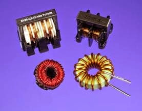
A selection of inductors designed for through- hole mounting is shown in Figure 14-2.
Figure 14-2. Four inductors designed for through-hole insertion into printed circuit boards.
How It Works
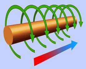
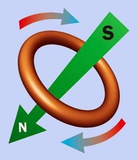
Direct current passing through an electrical conductor, such as a wire, creates a magnetic field around the conductor. In Figure 14-3, conventional current (flowing from positive to negative) is passing through a straight wire from left to right, as indicated by the red/blue arrow. The resulting magnetic field is indicated by the green arrows. If the wire is now bent into a curve, as shown in Figure 14-4, the magnetic field exerts an aggregate force downward through the curve. This magnetic force is conventionally said to flow from south to north.
If direct current could be induced to circulate through an unbroken circle of wire, the resulting magnetic field could exert a force through the circle as shown in Figure 14-5, assuming clock wise circulation of conventional current as suggested by the red/blue arrows.
Conversely, if a magnet was pushed through the center of the circle, it would induce a pulse of electric current in the circle. Thus, electricity passing through a wire can induce a magnetic field around the wire, and conversely, a magnet moving near a wire can induce an electric current
Figure 14-3. Conventional current passing through a wire from left to right (as indicated by the red/blue arrow) in- duces a magnetic field around the wire (shown by the green arrows).
Figure 14-4. If the wire is bent into a curve, the magnetic fields can create a net force shown by the large green arrow.
in the wire. This principle is used in an electrical generator, and also in a transformer, where alternating current in the primary coil induces a fluctuating magnetic field in the core, and the field in the core is turned back into alternating current in the secondary coil.
Note that a static or unchanging magnetic field will not induce a flow of electricity.
Figure 14-5. Hypothetically, if conventional current flows around a circular conductor (as suggested by the red/ blue arrows), it will create a magnetic field that can create
a force as shown by the green arrow.
DC Through a Coil
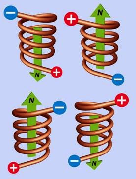
If the wire is formed into a helix (a series of approximate circles) as shown in Figure 14-6, and if DC current is passed through the wire, the aggregate of the magnetic fields can create a force in the direction of the green arrow in each ex ample, depending whether the wire is wound clockwise or counter-clockwise, and depending on the direction of the current. The helix is usually referred to as a coil or a winding.
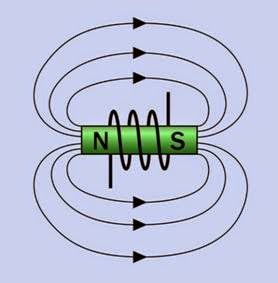
In actuality, a magnetic field is not open-ended, and its lines of force are completed by circling around outside the inductor, to complete a magnetic circuit. This completion of the field can be demonstrated by the traditional high-school experiment of positioning a compass or scattering iron filings on a sheet of paper above a magnet. A simplified depiction of lines of force completing a magnetic circuit is shown in Figure 14-7,
Figure 14-6. When DC current flows through a coil, it cre- ates magnetic fields that will exert a force whose directiondepends on the direction of the current and on whether the coil is wound clockwise or counterclockwise. The force is shown by the green arrow in each case.
where a coil is inducing the magnetic field. Note that throughout this encyclopedia, the color green is used to indicate the presence of magnetic force.
The completion of a magnetic field is not relevant to the primary function of the inductor. In fact the external part of the magnetic field is mostly a source of trouble in electronics applications, since it can interact with other components, and may necessitate the use of magnetic shielding. In addition, the field is weakened by completing itself through air, as air presents much greater reluctance (the magnetic equivalent of resistance) than the core of an electromagnet.
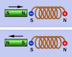
The polarity of a magnetic field created by a coil can be demonstrated by moving a small permanent magnet toward the coil, as shown in
Figure 14-7. A magnetic field in reality is not open-ended, and each line of force traveling through a rod-shaped magnet or electromagnet is completed outside of the magnet. The completion of magnetic fields has been omitted from other diagrams here for clarity.
Figure 14-8. If the magnet has opposite polarity to the coil, it will tend to be repelled, as like poles repel. If it has the same polarity, it will tend to be attracted, because opposite poles attract. This principle may be used in solenoids.
Figure 14-8. A permanent magnet (left) will either be drawn toward a DC-energized coil or repelled from it, de- pending on the polarity of the two magnetic fields.
Magnetic Core
The inductive power of a coil will be enhanced, and the saturation point will be reduced, by using a magnetic core. The term “magnetic” in this context does not mean that the core is a perma nent magnet; it means that the core can be magnetized briefly by a transient pulse of electricity through the surrounding coil.
A core enhances the effectiveness of an inductor because it has a lower reluctance than that of air. In other words, magnetic flux will flow much more readily through the core than through air.
Roughly speaking, the permeability of a magnetic circuit is the opposite of reluctance; it is a measure of how easily a magnetic field can be induced, and is usually expressed relative to the permeability of air, which is approximately 1. The permeability of different core types is discussed in the following “Values” section.
The core of the coil contains magnetic domains that behave as tiny magnets, with north and south poles. In the absence of a polarizing magnetic field, the domains are randomly aligned. As a magnetic field is introduced around them and grows stronger, the domains align themselves with it, increasing the total magnetic force. When the domains are almost all uniformly aligned, the core approaches magnetic saturation and ceases adding to the net magnetic field. At this point the current in the inductor is said to be continuous.
When power to the coil is disconnected, the do mains revert partially to their previous random orientation. Thus the core remains a weak permanent magnet. This effect is known as hystere sis, while the weak residual field is known as remanent magnetism.
EMF and Back-EMF
When DC current is connected through an inductor, the creation of a magnetic field takes a brief but measurable period of time. The field induces an EMF (electro-motive force) in the wire. Since this force opposes the supplied current, it
is referred to as back-EMF. It lasts only so long as the field is increasing to its full strength. After the field reaches a steady state, current flows through the coil normally.
This transient resistive effect is caused by the self- inductance of the coil, and is opposite to the behavior of a capacitor, which encourages an initial inrush of direct current until it is fully charged, at which point it blocks subsequent current flow.
When high-frequency alternating current at tempts to flow through an inductor, if each pulse is too brief to overcome the back-EMF, the coil will block the current. A coil can thus be designed to block some frequencies but not others.
Even a simple electrical circuit that does not contain a coil will still have some self-inductance, simply because the circuit consists of wires, and even a straight length of wire induces a magnetic field when the power is switched on. However, these inductive effects are so small, they can generally be ignored in practical applications.
The transient electrical resistance to alternating current caused by either an inductor or a capacitor is known as reactance, although it occurs un der opposite electrical conditions, as the coil impedes an initial pulse of DC current and then gradually allows it to pass, while a capacitor al lows an initial pulse of DC current and then impedes it.
When a flow of DC current through a coil is switched off, the magnetic field that was created by the coil collapses and releases its stored energy. This can cause a pulse of forward EMF, and like back-EMF, it can interfere with other components in a circuit. Devices such as motors and large relays that contain substantial coils can create problematic spikes of back-EMF and forward- EMF. The forward-EMF that occurs when power to the coil is interrupted is typically dealt with by putting a diode in parallel with the coil, allowing current to circulate through it. This is known as clamping the voltage transient. A diode-
capacitor combination known as a snubber is also commonly used. For a schematic and additional information on this topic, see “Snubber” (page 108).
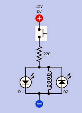
A schematic to demonstrate EMF and back-EMF is shown in Figure 14-9. The coil can be a 100-foot spool of 26-gauge (or smaller) hookup wire, or magnet wire. It will function more effectively if a piece of iron or steel, such as half-inch galvanized pipe, is inserted through its center. When the button is pressed, current is briefly impeded by the back-EMF created by the coil, and is diverted through D1, making it flash briefly. Then the coil’s reactance diminishes, allowing the current to flow through the coil and bypass the LED. When the pushbutton is released, the coil’s magnetic field collapses, and the consequent forward-EMF circulates through D2, causing it to flash briefly. Note that the polarity of back-EMF and forward- EMF are opposite, which is why the LEDs in the circuit are oriented with opposite polarities.
The 220Ω resistor should be rated at 1/4 watt minimum, and the button should not be held down for long, as the electrical resistance of the coil is relatively low. The LEDs ideally should be rated for a minimal forward current of no more than 5mA.
Electrical and Magnetic Polarity
Various mnemonics and images have been created to assist in memorizing the polarity or direction of the magnetic field that will be created
by a flow of electricity. The right-hand rule suggests that if the fingers of the right hand are curled around a coil in the same direction in which the turns of the coil were wound, and if conventional DC current also flows in this direction, the extended thumb will point in the direction of the principal force that can be created by the magnetic field.
By convention, the magnetic field is oriented from south to north, which can be remembered since the north end of the magnetic field will be
Figure 14-9. A test circuit to demonstrate the EMF and back-EMF created when DC current starts and stops passing through a coil. See text for details.
the negative end of the coil (north and negative both beginning with letter N). This mnemonic only works if conventional (positive) current flows through a coil that is wound clockwise.
Another model is the “corkscrew rule” in which we imagine conventional DC current flowing from the handle of a corkscrew, down through its metal section, toward the pointed end. If the corkscrew is turned clockwise, in the same direction as the electricity, the corkscrew will sink into the cork in the same as the direction as the re sulting magnetic force.
Variants
Variants include core materials, core shapes, terination style (for through-hole mounting in
perforated board, or for surface-mount), and external finish (some inductors are dipped in insulating material, while others allow their copper magnet wire to be exposed).
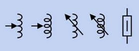
In addition there are two functional variants: variable inductors and ferrite beads. Their schematic symbols are shown in Figure 14-10.
Figure 14-10. Schematic symbols for a ferrite bead (farthest right) and variable inductors (all other symbols, which are functionally identical).
Magnetic Cores
A magnetic core may be made from solid iron, plates of iron or steel separated by thin insulating material, powdered iron mixed with a binder, or a ferrite compound derived from nickel, zinc, manganese, or a combination. An iron core has at least 1,000 times the permeability of air, while some ferrites are 10,000 times as permeable.
One major disadvantage of a magnetic core is hysteresis, which in this context refers to the tendency of the core to retain some magnetic “memory” as a cycle of alternating current changes from positive to negative. This residual magnetism must be overcome by the next positive pulse of AC. The tendency of the core to re tain magnetic polarity is known as its retentivity. Iron cores are especially retentive.
Another disadvantage of some magnetic cores is that they may host eddy currents induced by the magnetic field of the coil. These electrical cur rents tend to circulate through the core, reducing efficiency by generating waste heat, especially if coil currents are high. Forming a core from iron or steel plates, separated by thin layers of insulation, will inhibit these currents. Powdered iron
inhibits eddy currents because the particles have limited contact. Ferrites are nonconductive, and are therefore immune to eddy currents. They are widely used.
Hysteresis and eddy currents both incur energy losses with each AC cycle. Therefore, the losses increase linearly as the AC frequency increases. Consequently, inductor cores that suffer either of these problems are not well-suited to high frequencies.
Nonmagnetic Cores
The problems associated with magnetic cores may be avoided by winding the coil around a nonmagnetic core that may be hollow, ceramic, or plastic. A hollow core is referred to as an air core. The permeability of ceramic and plastic cores is close to that of air.
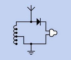
An inductor with a nonmagnetic core will be immune to eddy currents and retentivity, but will have to be significantly larger than a magnetic- cored coil with comparable inductance. In the case of a very primitive radio receiver, such as a crystal set, the air-cored coil that selects a radio frequency may be several inches in diameter. A basic circuit diagram for a crystal set (so-called because it uses a diode containing a germanium crystal) is shown in Figure 14-11. The antenna, at top, receives signals broadcast from radio stations. The coil can be tapped (as indicated by the black dots) as a simple way to select different in ductance values, blocking all but a narrow range of frequencies. The T-shaped white component at right is a high-impedance earphone. The diode blocks the lower half of the alternating current in a radio signal, and since the signal is amplitude- modulated, the earphone responds to variations in intensity in the signal and reproduces the sound encoded in it.
Figure 14-11. An early and basic application for an induc- tor is to select radio-station frequencies, as in this schematic for a crystal set. See text for details.
Variable Inductors
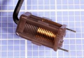
A variable inductor, also known as an adjustable inductor, is relatively uncommon but can be fabricated by using a magnetic core that penetrates the center of the inductor on an adjustable screw thread. The inductance of the assembly will in crease as a larger proportion of the magnetic core penetrates into the open center of the coil. A photograph of a variable inductor is at Figure 14-12.
Figure 14-12. A variable inductor. Its inductance is adjusted via a screw thread that varies the insertion of the core in the coil. In this component the core is turned by inserting a hex wrench, as shown. It is rated from 0.09μH to 0.12μH.
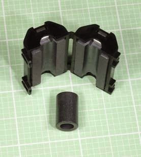
A ferrite bead inverts the design of a typical inductor by running a wire through a hole in the center of the bead, instead of coiling the wire around the core. Two ferrite beads are shown in Figure 14-13. At top, the bead is divided into two sections, each mounted in one-half of a plastic clam shell, which can be closed around a wire. At bottom, the bead must be threaded onto a wire. The purpose is either to limit radio-frequency radiation from a wire by absorbing it into the bead (where it is transformed into heat), or to protect a wire from external sources of radio-frequency radiation. Computer cabling to external devices; lamp dimmers; and some types of motors can be sources of radio frequency.
Figure 14-13. Two examples of ferrite beads. They can inhibit radio-frequency radiation from a wire, or protect the wire from interference.
Toroidal Cores
The magnetic circuit created by a rod-shaped core must be completed by the lines of force traveling back around from one end of the rod to the other, through the surrounding air. Since air has low permeability, this is a major source of in
efficiency. By comparison, a torus (a geometrical shape resembling a donut) completes the entire magnetic circuit inside its core. This significantly increases its efficiency. Also, because its field is better contained, a toroidal inductor needs little or no shielding to protect other components from stray magnetic effects.
Two through-hole toroidal inductors are shown in Figure 14-2. Bottom left: Rated at 345μH. Bot tom right: Rated at 15μH. The one at bottom-left has pins beneath it for insertion into a printed circuit board.
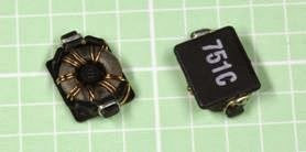
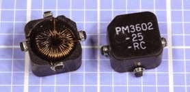
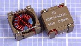
Surface-mount inductors often are toroidal to maximize the efficiency of a component that has to function on a very small scale. Examples are shown in Figure 14-14, Figure 14-15, and Figure 14-16.
Figure 14-14. In a typical toroidal inductor, the coil is wrapped around a magnetic core shaped as a torus. This surface-mount component (viewed from the bottom, at left, and from the top, at right) is at the low end of the range of component sizes. It is rated at 750nH.
Figure 14-15. A medium-sized surface-mount toroidal inductor (viewed from the bottom, at left, and from the top, at right). It is rated at 25μH.
Figure 14-16. A larger-sized surface-mount toroidal inductor (viewed from the bottom, at left, and from the top, at right). It is rated at 3.8μH.
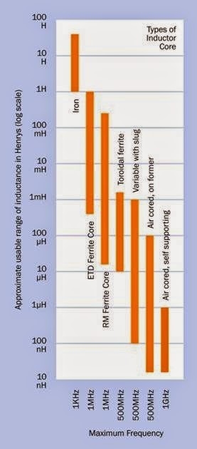
A chart showing some types of inductor cores, their commonly available inductances, and their maximum frequencies is shown in Figure 14-17.
Gyrator
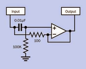
A gyrator is a small network, sometimes encapsulated in a silicon chip, using resistors, a semi conductor, and a capacitor to simulate some but not all of the behavior of a coil-based inductor. The semiconductor may be a transistor or a capacitor, depending on the specific circuit. A sample schematic is shown in Figure 14-18. Because no magnetic effects are induced, the gyrator is completely free from the problems of saturation and hysteresis, which affect coils with cores, and also produces no back-EMF. It simply attenuates a signal initially, and then gradually lowers its re actance, thus imitating this aspect of an inductor.
A gyrator may be used where a coil may be un acceptably large (as in a cellular phone) or where signal quality is of paramount importance—for example, in a graphic equalizer or other audio components that perform signal processing at input stages, such as preamplifiers.
Figure 14-17. Some commonly used inductor cores and their characteristics. Adapted from “Producing wound components” by R.Clark@surrey.ac.uk.
Figure 14-18. A possible schematic for a coil substitute known as a gyrator, which may be used where a conventional coil would be unacceptably bulky.
A gyrator does impose some limits on circuit de sign. While neither side of a real inductor needs to be at ground potential, a gyrator does require a ground connection. However, the performance advantages of gyrators are significant, as they can emulate high inductance without parasitic effects, can be more accurately calibrated (leading to more predictable performance), and do not create magnetic fields that can interfere with other components.
Values
Calculating Inductance
The magnetic inductance of a coil is measured with a unit known as the Henry, named after Jo seph Henry, a pioneer in electromagnetism. It is defined by imagining a coil in which current is fluctuating, causing the creation of EMF. If the rate of fluctuation is 1 amp per second and the induced EMF is 1 volt, the inductance of the coil is 1 Henry.
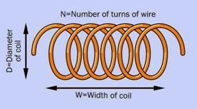
The letter L is commonly used to represent in ductance. To derive a useful formula, L will be expressed in microhenrys. If D is the diameter of a coil, N is the number of turns of wire, and W is
the width of coil (when the windings are viewed from the side, as shown in Figure 14-19), the pre cise relationship of the variables is complex but can be reduced to an approximate formula:
L = approx (D2 * N2) / 18 * D) + (40 * W
Figure 14-19. Dimensions of a coil, referenced by a for- mula to calculate its approximate inductance. See text for details.
From this, it is clear that inductance tends to in crease with coil diameter, and also increases (more significantly) with the square of the num ber of turns. If the number of turns remains con stant, inductance will be higher for a coil that is short and fat than for a coil that is narrow and long.
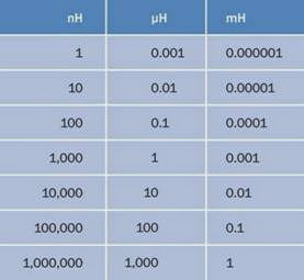
Because the Henry is a large unit, inductors in electronics circuits typically have their inductances measured in millihenrys (mH), microhenrys (μH), and nanohenrys (nH), where 1H = 1,000mH, 1 mH = 1,000μH, and 1μH = 1,000 nH. This rela tionship is shown in Figure 14-20.
Calculating Reactance
The reactance of an inductor (that is, its dynamic resistance to alternating current) varies with the frequency of the current. If f is the AC frequency (in Hertz), and L is the inductance (in Henrys), the reactance, XL in ohms, is given by the formula:
XL = 2 * π * f * L
From this equation, it’s apparent that as the frequency tends toward zero (DC current), or if the inductance tends toward zero (a short piece of
Figure 14-20. Inductance is typically measured in nanohenrys (nH), microhenrys (μH), and millihenrys (mH). Equivalent values in these units are shown here.
straight wire), the reactance will tend toward zero. Conversely, the inductor will impede cur rent increasingly as the frequency and/or the in ductance increases.
Calculating Reluctance
The letter S is often used to represent reluctance, while Greek letter μ customarily represents per meability (not to be confused with the use of μ as a multiplication factor of 1/1,000,000, as in μF, meaning “microfarad”). If A is the area of cross- section of the magnetic circuit and L is its length:
Datasheet Terminology
A typical manufacturer’s datasheet should in clude an inductance index for an inductor, ex pressed in μH per 100 turns of wire (assuming the wire is in a single layer) for inductors with a pow dered iron core, and mH per 1,000 turns of wire for inductors with ferrite cores.
The DCR is the DC resistance of an inductor, de rived purely from the wire diameter and its length.
The SRF is the self-resonant frequency. An induc tor should be chosen so that AC current passing through it will never get close to that frequency.
ISAT (or Isat) is the saturation current, which re sults in a magnetic core losing its function as a result of magnetic saturation. When this occurs, inductance drops and the charge current rate in creases drastically.
Series and Parallel Configurations Because the inductance of a coil conducting DC current is proportional to the current, the calcu lations to derive the total inductance of coils in
series or in parallel are identical to the calcula
tions used for resistors.
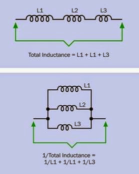
In series, all the coils inevitably pass the same current, and the total inductance is therefore found by summing the individual inductances. When coils are wired in parallel, the current dis tributes itself according to the inductances; therefore, if L1 is the reluctance of the first coil, L2 is the reluctance of the second coil, and so on, the total reluctance L of the network is found from the formula:
1/L = 1/L1 + 1/L2 + 1/L3. . .
This is shown in Figure 14-21. In reality, differ ences between the coils (such as their electrical resistance), and magnetic interaction between the coils, will complicate this simple relationship.
Time Constant
Just as the time constant of a capacitor defines the rate at which it accumulates voltage when power is applied through a resistor, the time con stant of an inductor defines the rate at which it gradually allows amperage to pass through it, overcoming the EMF generated by the coil. In both cases, the time constant is the number of seconds that the component requires to acquire approximately 63% of the difference between its current value and its maximum value. In the case of an inductor, suppose we assume zero internal resistance in the power source, zero resistance in
Figure 14-21. Calculating the total inductance of induc- tors in parallel (top) and series (bottom).
the coil windings, and an initial current of zero. If L is the inductance of the coil and R is the value of the series resistor, then the time constant—TC
—is given in seconds by the formula
TC = L / R
Therefore a coil of 10 millihenrys (0.01 Henry) in series with a 100-ohm resistor will pass 63% of the full current in 0.0001 seconds, or 1/10 of a millisecond; it will take an equal additional amount of time for the current to rise by another 63% of the remaining difference between its charge and the maximum amperage of the cir uit. In theory, the reactance of a coil can never diminish to zero, but in practice, five time con stants are considered adequate to allow maxi mum current flow.
How to Use it
Because the inductance of an inductor peaks as current increases, and then gradually diminishes,
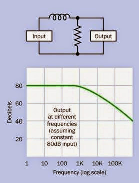
an inductor can be used to block or attenuate high frequencies. A circuit that does this is often referred to as a low-pass filter. The schematic and a graph suggesting its performance are shown in Figure 14-22. A basic application could be the crossover network in a loudspeaker system, where high-frequency signals are blocked from a low-frequency driver and are diverted to a high-frequency driver.
Figure 14-22. By using the ability of an inductor to block a range of frequencies, a low-pass filter blocks higher fre- quencies.
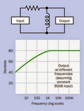
If the location of the inductor is shifted so that it shunts the signal away from the output, the re sults are reversed, and the circuit becomes a high-pass filter. The schematic and a graph sug gesting its performance are shown in Figure 14-23.
Note that capacitors may also be used to create frequency filters, but because their function is roughly inverse to that of inductors, the place
Figure 14-23. Here the inductor diverts low frequencies away from the output, allowing high frequencies to pass through.
ment of a capacitor in a circuit would be opposite to the placement of the inductor. Examples of filter circuits using capacitors are found in the entry for that component in this encyclopedia.
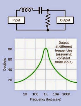
An inductor can be combined with a capacitor to form a bandpass filter, as shown in Figure 14-24. In this configuration, the inductor blocks the high frequencies while the capacitor blocks the low frequencies, allowing only a limited band of frequencies to get through.
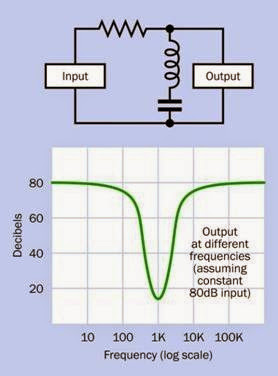
Once again if the location of the components is shifted to shunt the signal away from the output, the results are reversed, as shown in Figure 14-25. This is known as a notch filter.
The performance of these filters will depend on the component values, and in most applications, additional components will be necessary. So phisticated filter circuits are outside the scope of this encyclopedia.
Figure 14-24. If the values of a capacitor and an inductor are correctly chosen, and the components are placed in series, the inductor blocks high frequencies while the ca- pacitor blocks low frequencies, creating a bandpass filter, in which only a narrow band of frequencies can get through.
Inductors are of great importance in DC-DC con verters and AC-DC power supplies where volt age changes are enabled by rapid switching. See the relevant entries of this encyclopedia for additional details.
Generally, as electronic equipment has become increasingly miniaturized, the unavoidable bulk of inductors has limited their application. How ever they may still be used to tune oscillators, to block sudden spikes in power supplies, and to protect equipment from sudden voltage spikes (they are used, for example, in surge suppressors for computing equipment).
Figure 14-25. Here the capacitor and inductor block all frequencies except a narrow band, which they divert from the output. The result is a notch filter.
Core Choices
Air-cored inductors have relatively low induc tance, because of their low permeability. How ever, they can be operated at very high frequencies up to the gigahertz range, and can tolerate higher peak currents.
Inductors with an iron core suffer increasing power losses due to hysteresis and eddy currents as the AC frequency passing through the induc tor increases. Consequently, iron-cored induc tors are not suitable for frequencies much above 10KHz.
Miniaturization
A low-value inductor can be formed by etching a spiral onto a circuit board, in applications where size must be minimized. They may also beincor porated in integrated circuit chips. However, in small devices such as cellular phones, it is more common to use a coil substitute such as a gyra tor, as described previously.
What Can Go Wrong
Real-World Defects
The theoretically ideal inductor has no resistance or capacitance and suffers no energy losses. In reality, an inductor possesses both resistance and capacitance, also creates electrical noise, and may pick up electrical noise. It tends to create stray magnetic fields, and generally is more troublesome to deal with than its two cousins, the resistor and the capacitor.
Parasitic capacitance occurs between adjacent turns of wire. This capacitance becomes more significant at higher frequencies, leading ultimately to a situation where the coil becomes self resonant.
The workarounds for these problems involve coil geometries and choices of core material that go beyond the scope of this encyclopedia.
A gyrator should be considered as a possible substitute where inductors are troublesome or excessively expensive.
Saturation
Inductance increases as the current passing through a coil increases, but if a magnetic core is used, its contribution to inductance will stop abruptly when the core becomes magnetically saturated. In other words, when all of the ran domly distributed magnetic domains in the core have been induced to align themselves with the pervasive magnetic field, the core cannot be come more highly magnetized, and ceases to contribute to the inductance. Note that as a core approaches saturation levels, its hysteresis in creases because reversing its magnetization re quires greater energy. Antidotes to saturation would include a larger core, a lower current, a smaller number of turns in the coil, and using a core with lower permeability (such as air).
RF Problems
Radio frequencies (RF) introduce various problems affecting the efficiency of inductors. The skin effect is the tendency of high-frequency AC current to flow primarily on the surface of a strand of wire. The proximity effect refers to the tendency of the magnetic fields caused by adja cent wires to introduce eddy currents in the coil.
Both of these effects increase the effective resistance of the coil. Various coil geometries have been developed to minimize these effects, but are outside the scope of this encyclopedia. The fundamental lesson is that coils specifically de signed for RF are the only ones that should be used with RF.


