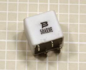
A fuse protects an electrical circuit or device from excessive current when a metal element inside it melts to create an open circuit. With the exception of resettable fuses (discussed separately in “Resettable Fuses” (page 24)), a fuse must be dis carded and replaced after it has fulfilled its function.
When high current melts a fuse, it is said to blow or trip the fuse. (In the case of a resettable fuse, only the word trip is used.)
A fuse can work with either AC or DC voltage, and can be designed for almost any current. In residential and commercial buildings, circuit break ers have become common, but a large cartridge fuse may still be used to protect the whole sys tem from short-circuits or from overcurrent caused by lightning strikes on exposed power lines.
In electronic devices, the power supply is al most always fused.
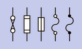
Schematic symbols for a fuse are shown in Figure 4-1. Those at the right and second from right are most frequently used. The one in the center is approved by ANSI, IEC, and IEEE but is seldom seen. To the left of that is the fuse symbol understood by electrical contractors in architectural plans. The symbol at far left used to be common but has fallen into disuse.
How It Works
The element in a fuse is usually a wire or thin metal strip mounted between two terminals. In a cartridge fuse, it is enclosed in a glass or ceramic cylinder with a contact at each end, or in a small metallic can. (Old-style, large, high-amperage fuses may be packaged in a paper or cardboard tube.) The traditional glass cartridge allows visual inspection to confirm that the fuse has blown.
A fuse responds only to current, not to voltage. When choosing a fuse that will be reliable in conditions of steady current consumption, a safe rule is to figure the maximum amperage when all components are functioning and add 50%. How ever, if current surges or spikes are likely, their duration will be relevant. If I is the current surge
in amps and t is its duration in seconds, the surge sensitivity of a fuse—which is often referred to verbally or in printed format as I2t—is given by the formula:
I2t = I2 * t
Some semiconductors also have an I2t rating, and should be protected with a similarly rated fuse.
Any fuse will present some resistance to the cur rent flowing through it. Otherwise, the current would not generate the heat that blows the fuse. Manufacturer datasheets list the voltage drop that the internal resistance of a fuse is likely to introduce into a circuit.
Values
The current rating or rated current of a fuse is usually printed or stamped on its casing, and is the maximum flow that it should withstand on a continuous basis, at the ambient temperature specified by the manufacturer (usually 25 degrees Centigrade). The ambient temperature refers to the immediate environment of the fuse, not the larger area in which it may be located. Note that in an enclosure containing other components, the temperature is usually significantly higher than outside the enclosure.
Ideally a fuse should function reliably and indefinitely at its rated maximum amperage, but should blow just as reliably if the current rises by approximately 20% beyond the maximum. In re ality, manufacturers recommend that continuous loading of a fuse should not exceed 75% of its rating at 25 degrees Centigrade.
The voltage rating or rated voltage of a fuse is the maximum voltage at which its element can be counted on to melt in a safe and predictable manner when it is overloaded by excess current. This is sometimes known as the breaking capacity. Above that rating, the remaining pieces of the fuse element may form an arc that sustains some electrical conduction.
A fuse can always be used at a lower voltage than its rating. If it has a breaking capacity of 250V, it will still provide the same protection if it is used at 5V.
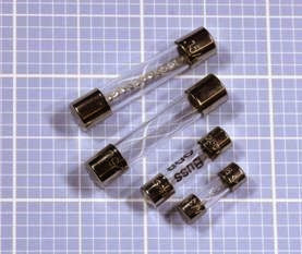
Four differently rated glass cartridge fuses are shown in Figure 4-2. The one at the top is a slow- blowing type, rated at 15A. Its element is de signed to absorb heat before melting. Below it is a 0.5A fuse with a correspondingly thinner element. The two smaller fuses are rated at 5A each. The center two fuses have a maximum voltage rating of 250V, while the one at the top is rated at 32V and the one at the bottom is rated at 350V. Clearly, the size of a fuse should never be used as a guide to its ratings.
Figure 4-2. Four glass cartridge fuses. See text for de- tails.
![clip_image001[1] clip_image001[1]](http://lh4.ggpht.com/--Fchl7bf35g/VEK5Jle_VDI/AAAAAAAAmyE/x2jNZPYHMV4/clip_image001%25255B1%25255D_thumb.gif?imgmax=800) Variants
Variants
Early power fuses in residential buildings consisted of bare nichrome wire wrapped around a porcelain holder. In the 1890s, Edison developed plug fuses in which the fuse was contained in a porcelain module with a screw thread, compatible with the base of an incandescent bulb. This design persisted in some U.S. urban areas for more than 70 years, is still found in old buildings, and is still being manufactured.
Small Cartridge Fuses
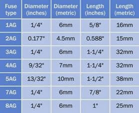
Small cartridge fuses for appliances and electronics equipment such as those shown in Figure 4-2–are available in sizes tabulated in Figure 4-3. With the exception of the 4.5mm diameter fuse (a European addition), these sizes were originally measured in inches; today, they are often described only with the equivalent metric measurement. Any cartridge fuse is usually available with the option of a lead attached to it at each end, so that it can be used as a through-hole component.
Figure 4-3. The approximate physical sizes of commonly used small glass or ceramic cartridge fuses are shown here with the codes that are often used to identify them.
Fuses may be fast acting, medium acting, or slow- blowing, the last of which may alternatively be referred to as delay fuses. Extra-fast–acting fuses are available from some manufacturers. The term SloBlo is often used but is actually a trademark of Littelfuse. None of the terms describing the speed of action of a fuse has been standardized with a specific time or time range.
Some cartridge fuses are available in a ceramic format as an alternative to the more common glass cylinder. If accidental application of extremely high current is possible (for example, in a multimeter that can be set to measure amps, and may be accidentally connected across a powerful battery), a ceramic cartridge is preferable because it contains a filler that will help to stop an arc from forming. Also, if a fuse is physically destroyed by application of very high cur rent, ceramic fragments may be preferable to glass fragments.
Automotive fuses are identifiable by their use of blades designed for insertion in flat sockets where the fuse is unlikely to loosen as a result of vibration or temperature changes. The fuses come in various sizes, and are uniformly color- coded for easy identification.
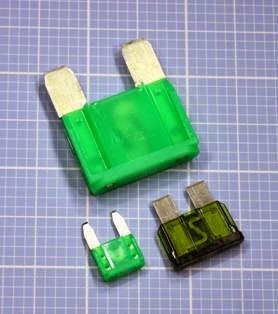
A selection of automotive fuses is shown in Figure 4-4. The type at the top is typically de scribed as a “maxi-fuse” while the type at bottom-left is a “mini-fuse.” Here again, size is ir relevant to function, as all three of those pictured are rated 30A at 32V.
Figure 4-4. Three automotive fuses. All have the same rating: 30A at 32V.
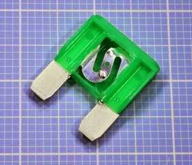
In Figure 4-5, the largest of the fuses from Figure 4-4 has been cut open to reveal its element.
Figure 4-5. The largest fuse from the previous figure, cut open to reveal its element.
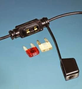
Usually automotive fuses are mounted together in a block, but if aftermarket accessory equipment is added, it may be protected by an inline fuse in a holder that terminates in two wires. This is shown with two sample fuses in Figure 4-6. Similar inline fuse holders are manufactured for other types of fuses.
Strip Fuses
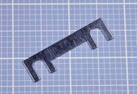
High-amperage fuses for vehicles may be sold in “strip fuse” format, also known as a fusible link, designed to be clamped between two screw- down terminals. Since some jumpers may look very similar, it is important to keep them separate. A strip fuse is shown in Figure 4-7.
Through-Hole Fuses
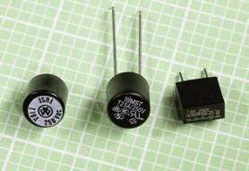
Small fuses with radial leads, which seem appropriate for through-hole insertion in printed circuit boards, are actually often used in conjunction with appropriate sockets, so that they can be easily replaced. They are described in catalogues as “subminiature fuses” and are typically found in laptop computers and their power sup plies, also televisions, battery chargers, and air conditioners. Three examples are shown in Figure 4-8. All have slow-blowing characteristics.
Figure 4-6. Two blade-type fuses, commonly used for automotive applications, shown with an inline fuse holder. The plastic cap, at right, is closed over the holder when a fuse has been installed.
Figure 4-7. This strip fuse is intended for use in diesel vehicles. The example shown is rated 100A at 36V.
Resettable Fuses
Properly known as a polymeric positive temperature coefficient fuse (often abbreviated PTC or PPTC), a resettable fuse is a solid-state, encapsulated component that greatly increases its resist ance in response to a current overload, but gradually returns to its original condition when the flow of current is discontinued. It can be thought
Figure 4-8. Three subminiature fuses terminating in wire leads. From left to right: 10A at 250V, 2.5A at 250V, and 5A at 250V.
of as a thermistor that has a nonlinear response. Three through-hole examples are shown in Figure 4-9. While different sizes of cartridge fuse may share the same ratings, differently rated re settable fuses may be identical in size. The one on the left is rated 40A at 30V, while the one on the right is rated 2.5A at 30V. (Note that the codes printed on the fuses are not the same as their manufacturer part numbers.) The fuse at the top is rated 1A at 135V.
When more than the maximum current passes through the fuse, its internal resistance increases suddenly from a few ohms to hundreds of thou sands of ohms. This is known as tripping the fuse. This inevitably entails a small delay, but is com parable to the time taken for a slow-blowing fuse to respond.
A resettable fuse contains a polymer whose crystalline structure is loaded with graphite particles that conduct electricity. As current flowing through the fuse induces heat, the polymer transitions to an amorphous state, separating the graphite particles and interrupting the conductive pathways. A small current still passes through the component, sufficient to maintain its amorphous state until power is disconnected.
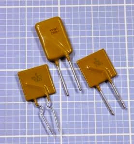 Figure 4-9. Some through-hole resettable fuses. See text for details.
After the resettable fuse cools, it gradually re crystallizes, although its resistance does not fall back completely to its original value for more than an hour.
The maximum safe level of current for a resettable fuse is known as the hold current, while the current that triggers its response is termed the trip current. Resettable fuses are available with trip-current ratings from 20mA to 100A. While conventional appliance and electronics fuses may be rated as high as 600V, resettable fuses are seldom rated above 100V.
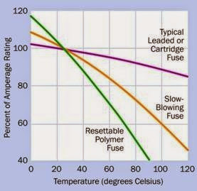
Typical cartridge fuses are affected only to a mi nor extent by temperature, but the current rating of a resettable fuse may diminish to 75% of its normal value at 50 degrees Centigrade and may drop to 50% of its normal value at 80 degrees Centigrade. In other words, a fuse that is rated for 4A at 25 degrees may tolerate a maximum of only 3A when it operates at twice that temperature. See Figure 4-10.
How to Use it
Figure 4-10. The three curves give a very approximate idea of the temperature sensitivity of three types of fuses commonly used to protect electronic equipment. The left- hand scale provides an approximate value for the amperage which will trip the fuse. Figure 4-11. A surface-mount resettable fuse. See text for
details.
Conventional slow-blowing fuses are temperature-sensitive, but to a lesser degree than resettable fuses.
Resettable fuses are used in computer power supplies, USB power sources, and loudspeaker enclosures, where they protect the speaker coils from being overdriven. They are appropriate in situations where a fuse may be tripped relatively often, or where technically unsophisticated users may feel unable to replace a fuse or reset a circuit breaker.
Brand names for resettable fuses include Poly Switch, OptiReset , Everfuse, Polyfuse, and Multi fuse. They are available in surface-mount (SMT) packages or as through-hole components, but not in cartridge format.
Surface Mount Fuses
Because surface-mount fuses are difficult or impossible to replace after they have been soldered onto the board, they are often resettable.A surface-mount resettable fuse approximately 0.3” square is shown in Figure 4-11. It is rated for 230V and has an internal resistance of 50 ohms. Its hold current is 0.09A and its trip current is 0.19A.
Figure 4-11. A surface-mount resettable fuse. See text for details.
How to Use it
Any equipment that may be plugged into a wall outlet should be fused, not only to protect its components but also to protect users who may open the box and start investigating with a screwdriver.
Equipment that contains powerful motors, pumps, or other inductive loads should be protected with slow-blowing fuses, as the initial surge of current when the equipment is switched on is likely to rise well above the rating of the fuse. A slow-blowing fuse will tolerate a surge for a couple of seconds. Other fuses will not.
Conversely, fast-acting fuses should be used with electronic equipment, especially integrated circuits that are quickly and easily damaged.
Any device using substantial battery power should be fused because of the unpredictable and generally bad behavior of batteries when they are short-circuited. Parallel connections be tween multiple large batteries should be fused
26 Encyclopedia of Electronic Components Volume 1
power > connection > fuse What Can Go Wrong
to avoid the possibility that a highly charged battery may attempt to recharge its neighbor(s). Large “J size” fuses rated from 125A to 450A have become common in the solar power community, where banks of lead-acid batteries are often used. These fuses have a thick brass tab at each end, drilled so that they can be bolted into place. Alternatively, they will push-fit into an appropri ate fuseholder.
For cartridge fuses up to 1/4” in diameter that don’t have leads attached, appropriately sized fuseholders are available in several formats:
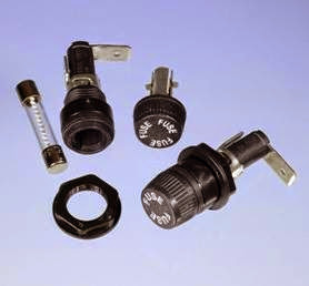
Panel mounted fuse enclosure is probably the most common, consisting of a plastic tube with a spring-contact at the bottom, and a plastic cap with a second contact inside. The cap either screws onto the tube of the fuse, or is pushed down and turned to hold it in place. A nut is pro vided to secure the fuseholder after it has been inserted into a hole drilled in the panel. The fuse is dropped into the tube, and the cap is applied. This type of holder is available in full-length or shorter, “low profile” formats. A low-profile hold er is shown in Figure 4-12. It is shown assembled at right, with its component parts disassembled alongside.
Figure 4-12. A low-profile panel-mounted fuse holder shown disassembled (left) and assembled (right).
Circuit board mounted fuse enclosure is basically the same as the panel-mounted version, but with through-hole solder pins attached.
Fuse block is a small plastic block with two clips on its upper surface for insertion of a cartridge fuse.
Fuse clips can be bought individually, with sol der pins for through-hole mounting.
Inline fuse holder is designed to be inserted in a length of wire. Usually made of plastic, it will either terminate it, wires or will have metal con tacts to crimp or solder at each end. See Figure 4-6.
Through-hole fuse holders are available for subminiature fuses.
What Can Go Wrong
Repeated Failure
When a fuse in a circuit blows frequently, this is known as nuisance opening. Often it can result from failure to take into account all the aspects of the circuit, such as a large filtering capacitor in a power supply that draws a major surge of cur rent when the power supply is switched on. The formally correct procedure to address this problem is to measure the power surge, properly known as peak inrush current, with an oscilloscope, calculate the I2 * t of the wave form, and select a fuse with a rating at least 5 times that value.
A fuse should never be replaced with anequiva lent length of wire or any other conductor.
Soldering Damage
When a through-hole or surface-mount fuse is soldered into place, heat from the soldering process can cause the soft metal element inside the fuse to melt partially and reflow. This is likely to change the rating of the fuse. Generally, fuses should be treated with the same caution as semiconductors when they are fixed in place with solder.
Placement
A fuse should be placed close to the power source or power input point in a circuit, so that it protects as much of the circuit as possible.

