This entry covers electrochemical power sources. Electricity is most often generated ectromagnetically, but since these sources cannot be classified as components, they are outside the scope of the encyclopedia. Electrostatic sources are excluded for similar reasons.
A battery is sometimes referred to as a cell or power cell, but can actually contain multiple cells, as defined in this entry. It used to be called an accumulator or a pile, but those terms are now archaic.
A battery contains one or more electrochemical cells in which chemical reactions create an electrical potential between two immersed terminals. This potential can be discharged as current passing through a load.
An electrochemical cell should not be confused with an electrolytic cell, which is powered by an external source of electricity to promote electrolysis, whereby chemical compounds are broken down to their constituent elements. An electro lytic cell thus consumes electricity, while an electrochemical cell produces electricity.
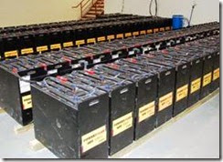
Batteries range in size from button cells to large lead-acid units that store power generated by solar panels or windmills in locations that can be off the grid. Arrays of large batteries can provide bridging power for businesses or even small communities where conventional power is un reliable. Figure 2-1 shows a 60KW, 480VDC self- watering battery array installed in a corporate data center, supplementing wind and solar sources and providing time-of-day peak shaving of energy usage. Each lead-acid battery in this array measures approximately 28” × 24” × 12” and weighs about 1,000 lb.
Figure 2-1. A battery array providing 60KW at 480VDC as backup for a corporate data center. (Photo by permission of Hybridyne Power Systems, Canada, Inc., and the Hy- bridyne group of companies. Copyright by Hybridyne, an internationally registered trademark of Hybridyne Power Systems Canada Inc. No right of further reproduction un- less specifically granted by Hybridyne.)
How It Works
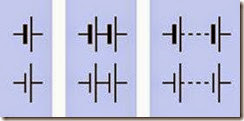
Schematic symbols for a battery are shown in Figure 2-2. The longer of the two lines represents the positive side of the battery, in each case. One way to remember this is by imagining that the longer line can be snipped in half so that the two segments can combine to form a + sign. Traditionally, multiple connected battery symbols in dicate multiple cells inside a battery; thus the center symbols in the figure could indicate a 3V battery, while those on the right would indicate a voltage greater than 3V. In practice, this con vention is not followed conscientiously.
Figure 2-2. Schematic symbols for a battery. Each pair of symbols within a blue rectangle is functionally identical.
 How It Works
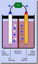
In a basic battery design often used for demon stration purposes, a piece of copper serves as an electrode, partially immersed in a solution of cop per sulfate, while a piece of zinc forms a second electrode, partially immersed in a solution of zinc sulfate. Each sulfate solution is known as an elec trolyte, the complete battery may be referred to as a cell, and each half of it may be termed a half- cell.
A simplified cross-section view is shown in Figure 2-3. Blue arrows show the movement of electrons from the zinc terminal (the anode), through an external load, and into a copper ter minal (the cathode). A membrane separator al lows the electrons to circulate back through the battery, while preventing electrolyte mixing.
Orange arrows represent positive copper ions. White arrows represent positive zinc ions. (An ion is an atom with an excess or deficit of electrons.) The zinc ions are attracted into the zinc sulfate electrolyte, resulting in a net loss of mass from the zinc electrode.
Meanwhile, electrons passing into the copper electrode tend to attract positive copper ions, shown as orange arrows in the diagram. The cop per ions are drawn out of the copper sulfate elec trolyte, and result in a net accumulation of cop per atoms on the copper electrode.
This process is energized partially by the fact that zinc tends to lose electrons more easily than cop per.
Figure 2-3. A classically simple electrochemical cell. See text for additional details.
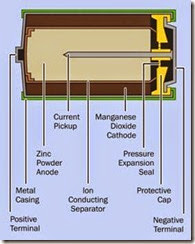
Batteries for use in consumer electronics typical ly use a paste instead of a liquid as an electrolyte, and have been referred to as dry cells, although this term is becoming obsolete. The two half- cells may be combined concentrically, as in a typical 1.5-volt C, D, AA, or AAA alkaline battery (see Figure 2-4).
Figure 2-4. Cross-section view of a typical 1.5-volt alka- line battery.
A 1.5V battery contains one cell, while a 6V or 9V battery will contain multiple cells connected in series. The total voltage of the battery is the sum of the voltages of its cells.
Electrode Terminology
The electrodes of a cell are often referred to as the anode and the cathode. These terms are con fusing because the electrons enter the anode in side the cell and leave it outside the cell, while electrons enter the cathode from outside the celland leave it inside the cell. Thus, the anode is an electron emitter if you look at it externally, but the cathode is an electron emitter if you look at it internally.
Conventional current is imagined to flow in the opposite direction to electrons, and therefore, outside the cell, this current flows from the cath ode to the anode, and from this perspective, the cathode can be thought of as being “more posi tive” than the anode. To remember this, think of the letter t in “cathode” as being a + sign, thus: ca+hode. In larger batteries, the cathode is often painted or tagged red, while the anode may be painted or tagged black or blue.
When a reusable battery is recharged, the flow of electrons reverses and the anode and the cath ode effectively trade places. Recognizing this, the manufacturers of rechargeable batteries may refer to the more-positive terminal as the anode. This creates additional confusion, exacerbated further still by electronics manufacturers using the term “cathode” to identify the end of a di ode which must be “more negative”(i.e., at a low er potential) than the opposite end.
To minimize the risk of errors, it is easiest to avoid the terms “anode” and “cathode” when referring to batteries, and speak instead of the negative and positive terminals. This encyclopedia uses the common convention of reserving the term “cathode” to identify the “more negative” end of any type of diode.
Variants
Three types of batteries exist.
1.Disposable batteries, properly (but infrequently) referred to as primary cells. They are not reliably rechargeable because their chemical reactions are not easily reversible.
2.Rechargeable batteries, properly (but in frequently) known as secondary cells. They can be recharged by applying a voltage between
the terminals from an external source such as a battery charger. The materials used in the battery, and the care with which the battery is maintained, will affect the rate at which chemical degradation of the electrodes gradually occurs as it is recharged repeated ly. Either way, the number of charge/ discharge cycles is limited.
1. Fuel Cells require an inflow of a reactive gas such as hydrogen to maintain an electro chemical reaction over a long period. They are beyond the scope of this encyclopedia.
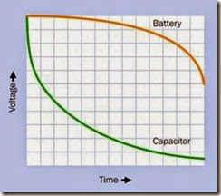
A large capacitor may be substituted for a bat tery for some applications, although it has a low er energy density and will be more expensive to manufacture than a battery of equivalent power storage. A capacitor charges and discharges much more rapidly than a battery because no chemical reactions are involved, but a battery sustains its voltage much more successfully dur ing the discharge cycle. See Figure 2-5.
Figure 2-5. The voltage drop of a discharging capacitor is much steeper initially than that of a battery, making ca- pacitors unsuitable as a battery substitute in many appli- cations. However, the ability of a capacitor to discharge very rapidly at high amperage can sometimes be a signifi- cant advantage.
Disposable Batteries
The energy density of any disposable battery is higher than that of any type of rechargeable bat tery, and it will have a much longer shelf life be cause it loses its charge more slowly during stor age (this is known as the self-discharge rate). Dis posable batteries may have a useful life of five years or more, making them ideal for applica tions such as smoke detectors, handheld re motes for consumer electronics, or emergency flashlights.
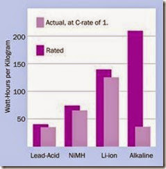
Disposable batteries are not well suited to deliv ering high currents through loads below 75Ω. Rechargeable batteries are preferable for higher- current applications. The bar chart in Figure 2-6 shows the rated and actual capabilities of an al kaline battery relative to the three most com monly used rechargeable types, when the bat tery is connected with a resistance that is low enough to assure complete discharge in 1 hour.
The manufacturer’s rating of watt hours per kilo is typically established by testing a battery with a relatively high-resistance load and slow rate of discharge. This rating will not apply in practice if a battery is discharged with a C-rate of 1, mean ing complete discharge during 1 hour.
Common types of disposable batteries are zinc- carbon cells and alkaline cells. In a zinc-carbon cell, the negative electrode is made of zinc while the positive electrode is made of carbon. The limited power capacity of this type of battery has reduced its popularity, but because it is the cheapest to manufacture, it may still be found where a company sells a product with “batteries included.” The electrolyte is usually ammonium chloride or zinc chloride. The 9V battery in Figure 2-7 is actually a zinc-carbon battery ac cording to its supplier, while the smaller one be side it is a 12V alkaline battery designed for use in burglar alarms. These examples show that bat teries cannot always be identified correctly by a casual assessment of their appearance.
Figure 2-6. Because of their relatively high internal resist- ance, alkaline batteries are especially unsuited to high dis- charge rates, and should be reserved for applications where a small current is required over a long period. (Chart derived from http://batteryuniversity.com.)
Figure 2-7. At left, a cheap carbon-zinc battery; at right, a 12V alkaline burglar-alarm battery. See text for additional details.
In an alkaline cell, the negative electrode is made of zinc powder, the positive electrode is manga nese dioxide, and the electrolyte is potassium hydroxide. An alkaline cell may provide between three to five times the power capacity of an equal size of zinc-carbon cell and is less susceptible to voltage drop during the discharge cycle.
Extremely long shelf life is necessary in some military applications. This may be achieved by using a reserve battery, in which the internal chemical compounds are separated from each other but can be recombined prior to use.
Rechargeable Batteries
Commonly used types are lead-acid, nickel cad mium (abbreviated NiCad or NiCd), nickel-metal hydride (abbreviated NiMH), lithium-ion (abbreviated Li-ion), and lithium-ion polymer.
Lead-acid batteries have existed for more than a century and are still widely used in vehicles, bur glar alarms, emergency lighting, and large power backup systems. The early design was described as flooded; it used a solution of sulfuric acid (generically referred to as battery acid) as its electro lyte, required the addition of distilled water periodically, and was vented to allow gas to escape. The venting also allowed acid to spill if the bat tery was tipped over.
The valve-regulated lead-acid battery (VRLA) has become widely used, requiring no addition of water to the cells. A pressure relief valve is in cluded, but will not leak electrolyte, regardless of the position of the battery. VRLA batteries are preferred for uninterruptible power supplies for data-processing equipment, and are found in automobiles and in electric wheelchairs, as their low gas output and security from spillage increases their safety factor.
VRLA batteries can be divided into two types: absorbed glass mat (AGM) and gel batteries. The electrolyte in an AGM is absorbed in a fiber-glass mat separator. In a gel cell, the electrolyte is mixed with silica dust to form an immobilized gel.
The term deep cycle battery may be applied to a lead-acid battery and indicates that it should be more tolerant of discharge to a low level—per haps 20 percent of its full charge (although man ufacturers may claim a lower number). The plates in a standard lead-acid battery are composed of a lead sponge, which maximizes the surface area available to acid in the battery but can be physically abraded by deep discharge. In a deep cycle battery, the plates are solid. This means they are more robust, but are less able to supply high am perage. If a deep-discharge battery is used to start an internal combustion engine, the battery should be larger than a regular lead-acid battery used for this purpose.
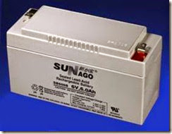
A sealed lead-acid battery intended to power an external light activated by a motion detector is shown in Figure 2-8. This unit weighs several pounds and is trickle-charged during the day time by a 6” × 6” solar panel.
Figure 2-8. A lead-acid battery from an external light ac- tivated by a motion sensor.
Nickel-cadmium (NiCad) batteries can withstand extremely high currents, but have been banned in Europe because of the toxicity of metallic cad mium. They are being replaced in the United States by nickel-metal hydride (NiMH) types, which are free from the memory effect that can prevent a NiCad cell from fully recharging if it has been left for weeks or months in a partially dis charged state.
Lithium-ion and lithium-ion polymer batteries have a better energy-to-mass ratio than NiMH batteries, and are widely used with electronic devices such as laptop computers, media play ers, digital cameras, and cellular phones. Large arrays of lithium batteries have also been used in some electric vehicles.
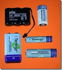
Various small rechargeable batteries are shown in Figure 2-9. The NiCad pack at top-left was manufactured for a cordless phone and is rapidly becoming obsolete. The 3V lithium battery at top-right was intended for a digital camera. The three batteries in the lower half of the photo graph are all rechargeable NiMH substitutes for 9V, AA, and AAA batteries. The NiMH chemistry results in the AA and AAA single-cell batteries being rated for 1.2V rather than 1.5V, but the manufacturer claims they can be substituted for 1.5V alkaline cells because NiMH units sustain their rated voltage more consistently over time. Thus, the output from a fresh NiMH battery may be comparable to that of an alkaline battery that is part-way through its discharge cycle.
Figure 2-9. Top left: NiCad battery pack for a cordless phone. Top right: Lithium battery for a digital camera. The other batteries are rechargeable NiMH substitutes for ev- eryday alkaline cells.
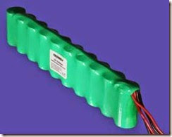
NiMH battery packs are available to deliver sub stantial power while being smaller and lighter than lead-acid equivalents. The NiMH package in Figure 2-10 is rated for 10Ah, and consists of ten
D-size NiMH batteries wired in series to deliver 12VDC. This type of battery pack is useful in ro botics and other applications where a small motor-driven device must have free mobility.
Figure 2-10. This NiMH battery pack is rated at 10Ah and delivers 12 volts from ten D-size cells wired in series.
Values
Amperage
The current delivered by a battery will be largely determined by the resistance of the external load placed between its terminals. However, because ion transfer must occur inside the battery to complete the circuit, the current will also be limi ted by the internal resistance of the battery. This should be thought of as an active part of the cir cuit.
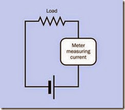
Since a battery will deliver no current if there is no load, current must be measured while a load is attached, and cannot be measured by a meter alone. The meter will be immediately overloa ded, with destructive results, if it is connected directly between the terminals of a battery, or in parallel with the load. Current must always be measured with the meter in series with the load, and the polarity of the meter must correspond with the polarity of the battery. See Figure 2-11.
Figure 2-11. When measuring current using an ammeter (or a multimeter configured to measure amps), the meter must be placed in series with the battery and a load. To avoid damaging the meter, it must never be applied di- rectly across the terminals of the battery, or in parallel with a load. Be careful to observe the polarity of the meter.
Capacity
The electrical capacity of a battery is measured in amp-hours, abbreviated Ah, AH, or (rarely) A/H. Smaller values are measured in milliamp-hours, usually abbreviated mAh. If I is the current being drawn from a battery (in amps) and T is the time for which the battery can deliver that current (in hours), the amp-hour capacity is given by the formula:
Ah = I * T
By turning the formula around, if we know the amp-hour rating that a manufacturer has deter mined for a battery, we can calculate the time in hours for which a battery can deliver a particular current:
T = Ah / I
Theoretically, Ah is a constant value for any given battery. Thus a battery rated for 4Ah should pro vide 1 amp for 4 hours, 4 amps for 1 hour, 5 amps for 0.8 hours (48 minutes), and so on.
In reality, this conveniently linear relationship does not exist. It quickly breaks down as the
current rises, especially when using lead-acid batteries, which do not perform well when re quired to deliver high current. Some of the cur rent is lost as heat, and the battery may be elec trochemically incapable of keeping up with de mand.
The Peukert number (named after its German originator in 1897) is a fudge factor to obtain a more realistic value for T at higher currents. If n is the Peukert number for a particular battery, then the previous formula can be modified thus:
T = Ah / In
Manufacturers usually (but not always) supply Peukert’s number in their specification for a bat tery. So, if a battery has been rated at 4Ah, and its Peukert number is 1.2 (which is typical for lead-acid batteries), and I=5 (in other words, we want to know for how long a time, T, the battery can deliver 5 amps):
T = 4 / 51.2 = approximately 4 / 6.9
This is about 0.58 hours, or 35 minutes—much less than the 48 minutes that the original formula suggested.
Unfortunately, there is a major problem with this calculation. In Peukert’s era, the amp-hour rating for a battery was established by a manufacturer by drawing 1A and measuring the time during which the battery was capable of delivering that current. If it took 4 hours, the battery was rated at 4Ah.
Today, this measurement process is reversed. In stead of specifying the current to be drawn from the battery, a manufacturer specifies the time for which the test will run, then finds the maximum current the battery can deliver for that time. Often, the time period is 20 hours. Therefore, if a battery has a modern 4Ah rating, testing has probably determined that it delivered 0.2A for 20 hours, not 1A for 4 hours, which would have been the case in Peukert’s era.
This is a significant distinction, because the same battery that can deliver 0.2A for 20 hours will not be able to satisfy the greater demand of 1A for 4 hours. Therefore the old amp-hour rating and the modern amp-hour rating mean different things and are incompatible. If the modern Ah rating is inserted into the old Peukert formula (as it was above), the answer will be misleadingly optimis tic. Unfortunately, this fact is widely disregarded. Peukert’s formula is still being used, and the per formance of many batteries is being evaluated incorrectly.
The formula has been revised (initially by Chris Gibson of SmartGauge Electronics) to take into account the way in which Ah ratings are estab lished today. Suppose that AhM is the modern rating for the battery’s capacity in amp-hours, H is the duration in hours for which the battery was tested when the manufacturer calibrated it, n is Peukert’s number (supplied by the manufactur er) as before, and I is the current you hope to draw from the battery. This is the revised formula to determine T:
T = H * (AhM / (I * H)n )
How do we know the value for H? Most (not all) manufacturers will supply this number in their battery specification. Alternatively, and confus ingly, they may use the term C-rate, which can be defined as 1/H. This means you can easily get the value for H if you know the C-rate:
H = 1 / C-rate
We can now use the revised formula to rework the original calculation. Going back to the exam ple, if the battery was rated for 4Ah using the modern system, in a discharge test that lasted 20 hours (which is the same as a C-rate of 0.05), and the manufacturer still states that it has a Peukert number of 1.2, and we want to know for how long we can draw 5A from it:
T = 20 * (4/(5 * 20)1.2) = approximately 20 * 0.021
This is about 0.42 hours, or 25 minutes—quite different from the 35 minutes obtained with the old version of the formula, which should never be used when calculating the probable discharge time based on a modern Ah rating. These issues may seem arcane, but they are of great importance when assessing the likely performance of battery-powered equipment such as electric vehicles.
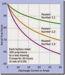
Figure 2-12 shows the probable actual performance of batteries with Peukert numbers of 1.1, 1.2, and 1.3. The curves were derived from the revised version of Peukert’s formula and show how the number of amp-hours that you can ex pect diminishes for each battery as the current increases. For example, if a battery that the man ufacturer has assigned a Peukert number of 1.2 is rated at 100Ah using the modern 20-hour test, but we draw 30A from it, the battery can actually deliver only 70Ah.
Figure 2-12. Actual amp-hour performance that should be expected from three batteries of Peukert numbers 1.1, 1.2, and 1.3 when they discharge currents ranging from 5 to 30 amps, assuming that the manufacturer has rated each battery at 100Ah using the modern system, which usually entails a 20-hour test (a C-rate of 0.05).
One additional factor: For any rechargeable bat tery, the Peukert number gradually increases with age, as the battery deteriorates chemically.
Voltage
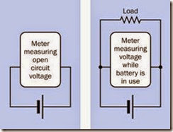
The rated voltage of a fully charged battery is known as the open circuit voltage (abbreviated OCV or Voc), defined as the potential that exists when no load is imposed between the terminals. Because the internal resistance of a volt meter (or a multimeter, when it is used to measure DC volts) is very high, it can be connected directly between the battery terminals with no other load present, and will show the OCV quite accurately, without risk of damage to the meter. A fully charged 12-volt car battery may have an OCV of about 12.6 volts, while a fresh 9-volt alkaline bat tery typically has an OCV of about 9.5 volts. Be extremely careful to set a multimeter to measure DC volts before connecting it across the battery. Usually this entails plugging the wire from the red probe into a socket separately reserved for measuring voltage, not amperage.
The voltage delivered by a battery will be pulled down significantly when a load is applied to it, and will decrease further as time passes during a discharge cycle. For these reasons, a voltage regulator is required when a battery powers components such as digital integrated circuit chips, which do not tolerate a wide variation in voltage.
To measure voltage while a load is applied to the battery, the meter must be connected in parallel with the load. See Figure 2-13. This type of meas urement will give a reasonably accurate reading for the potential applied to the load, so long as the resistance of the load is relatively low com pared with the internal resistance of the meter.
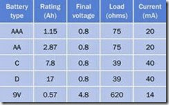
Figure 2-14 shows the performance of five com monly used sizes of alkaline batteries. The ratings in this chart were derived for alkaline batteries under favorable conditions, passing a small cur rent through a relatively high-ohm load for long periods (40 to 400 hours, depending on battery type). The test continued until the final voltage for each 1.5V battery was 0.8V, and the final volt age for the 9V battery was a mere 4.8V. These voltages were considered acceptable when the
Figure 2-13. When using a volt meter (or a multimeter configured to measure voltage), the meter can be applied directly between the battery terminals to determine the open-circuit voltage (OCV), or in parallel with a load to de- termine the voltage actually supplied during use. A multi- meter must be set to measure DC volts before connecting it across a battery. Any other setting may damage the me- ter.
Ah ratings for the batteries were calculated by the manufacturer, but in real-world situations, a final voltage of 4.8V from a 9V battery is likely to be unacceptable in many electronics applica tions.
Figure 2-14. The voltage delivered by a battery may drop to a low level while a manufacturer is establishing an amp- hour rating. Values for current, shown in the chart, were calculated subsequently as estimated averages, and should be considered approximate. (Derived from a chart published by Panasonic.)
As a general rule of thumb, if an application does not tolerate a significant voltage drop, the man ufacturer’s amp-hour rating for a small battery may be divided by 2 to obtain a realistic number.
How to Use it
When choosing a battery to power a circuit, considerations will include the intended shelf life, maximum and typical current drain, and battery weight. The amp-hour rating of a battery can be used as a very approximate guide to determine its suitability. For 5V circuits that impose a drain of 100mA or less, it is common to use a 9V battery, or six 1.5V batteries in series, passing current through a voltage regulator such as the LM7805. Note that the voltage regulator requires energy to function, and thus it imposes a voltage drop that will be dissipated as heat. The mini mum drop will vary depending on the type of regulator used.
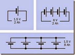
Batteries or cells may be used in series or in parallel. In series, the total voltage of the chain of cells is found by summing their individual voltages, while their amp-hour rating remains the same as for a single cell, assuming that all the cells are identical. Wired in parallel, the total voltage of the cells remains the same as for a single cell, while the combined amp-hour value is found by summing their individual amp-hour ratings, as suming that all the batteries are identical. See Figure 2-15.
In addition to their obvious advantage of portability, batteries have an additional advantage of being generally free from power spikes and noise that can cause sensitive components to misbe have. Consequently, the need for smoothing will depend only on possible noise created by other components in the circuit.
Motors or other inductive loads draw an initial surge that can be many times the current that they use after they start running. A battery must be chosen that will tolerate this surge without damage.
Figure 2-15. Theoretical results of using 1.5V cells in ser- ies or in parallel, assuming a 2Ah rating for one cell.
Because of the risk of fire, United States airline regulations limit the amp-hour capacity of lithium-ion batteries in any electronic device in carry-on or checked passenger baggage. If a de vice may be carried frequently as passenger bag gage (for example, emergency medical equip ment), NiMH batteries are preferred.
What Can Go Wrong
Short Circuits: Overheating and Fire
A battery capable of delivering significant cur rent can overheat, catch fire, or even explode if it is short-circuited. Dropping a wrench across the terminals of a car battery will result in a bright flash, a loud noise, and some molten metal. Even a 1.5-volt alkaline AA battery can become too hot to touch if its terminals are shorted together. (Never try this with a rechargeable battery, which has a much lower internal resistance, allowing much higher flow of current.) Lithium-ion bat teries are particularly dangerous, and almost al ways are packaged with a current-limiting com ponent that should not be disabled. A short- circuited lithium battery can explode.
If a battery pack is used as a cheap and simple workbench DC power supply, a fuse or circuit breaker should be included. Any device that uses significant battery power should be fused.
Diminished Performance Caused by Improper Recharging
Many types of batteries require a precisely meas ured charging voltage and a cycle that ends au tomatically when the battery is fully charged. Failure to observe this protocol can result in chemical damage that may not be reversible. A charger should be used that is specifically in tended for the type of battery. A detailed com parison of chargers and batteries is outside the scope of this encyclopedia.
Complete Discharge of Lead-Acid Battery
Complete or near-complete discharge of a lead- acid battery will significantly shorten its life (un less it is specifically designed for deep-cycle use
—although even then, more than an 80% dis charge is not generally recommended).
Inadequate Current
Chemical reactions inside a battery occur more slowly at low temperatures. Consequently, a cold battery cannot deliver as much current as a warm battery. For this reason, in winter weather, a car battery is less able to deliver high current. At the same time, because engine oil becomes more viscous as the temperature falls, the starter mo tor will demand more current to turn the engine. This combination of factors explains the tenden cy of car batteries to fail on cold winter mornings.
Incorrect Polarity
If a battery charger or generator is connected with a battery with incorrect polarity, the battery may experience permanent damage. The fuse or circuit breaker in a charger may prevent this from occurring and may also prevent damage to the charger, but this cannot be guaranteed.
If two high-capacity batteries are connected with opposite polarity (as may happen when a clumsy attempt is made to start a stalled car with jumper cables), the results may be explosive. Never lean over a car battery when attaching cables to it, and ideally, wear eye protection.
power > source > battery
Reverse Charging
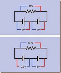
Reverse charging can occur when a battery be comes completely discharged while it is wired (correctly) in series with other batteries that are still delivering current. In the upper section of the schematic at Figure 2-16 two healthy 6V batter ies, in series, are powering a resistive load. The battery on the left applies a potential of 6 volts to the battery on the right, which adds its own 6 volts to create a full 12 volts across the load. The red and blue lines indicate volt meter leads, and the numbers show the reading that should be observed on the meter.
In the second schematic, the battery on the left has become exhausted and is now a “dead weight” in the circuit, indicated by its gray color. The battery on the right still sustains a 6-volt po tential. If the internal resistance of the dead bat tery is approximately 1 ohm and the resistance of the load is approximately 20 ohms, the poten tial across the dead battery will be about 0.3 volts, in the opposite direction to its normal charged voltage. Reverse charging will result and can damage the battery. To avoid this problem, a battery pack containing multiple cells should never be fully discharged.
Sulfurization
When a lead-acid battery is partially or com pletely discharged and is allowed to remain in that state, sulfur tends to build up on its metal plates. The sulfur gradually tends to harden, forming a barrier against the electrochemical re actions that are necessary to recharge the bat tery. For this reason, lead-acid batteries should not be allowed to sit for long periods in a dis charged condition. Anecdotal evidence sug gests that even a very small trickle-charging cur rent can prevent sulfurization, which is why some people recommend attaching a small solar panel to a battery that is seldom used—for example, on a sail boat, where the sole function of the bat tery is to start an auxiliary engine when there is insufficient wind.
Figure 2-16. When a pair of 6V batteries is placed in ser- ies to power a resistive load, if one of the batteries dis- charges completely, it becomes a load instead of a power source, and will be subjected to reverse charging, which may cause permanent damage.

