Electromagnetic Waves
This chapter, especially in the middle part, is very calculus intensive. Depending on your course you may want to be selective of the sections you read. If your course does not deal with the derivations of the speed and energy transport in an electromagnetic wave, you may want to pass over or skim the sections on “The Speed of the Wave” and “Energy Transport in Electromagnetic Waves.” While the understanding of how electromagnetic waves are propagated is fairly complicated, many of the problems are quite simple. Because the understanding of how waves propagate is so important, and fairly difficult to understand, we will develop the ideas underpinning electromagnetic wave propagation in some detail.
Generating Waves
There is a broad spectrum of electromagnetic waves generated in a variety of ways. For convenience in discussion we will, however, concentrate on waves generated from an oscillating L-C circuit. The circuit shown in Fig. 43-1 is an L-C circuit with some additions.
Fig. 43-1
The L-C circuit has components that produce resonance with a frequency suitable for a radio transmitter (a typical radio frequency of 300 kHz corresponds to a wavelength of 1.0 m). The energy source keeps the circuit oscillating. The inductor consists of a primary and secondary, with the secondary connected to a resistor. At the natural resonance frequency of the L-C circuit, the voltage across the resistor is sinusoidal. If a wire (antenna) is substituted for this resistor, then a sinusoidal voltage appears across the antenna. This is not a complete description of a radio transmitter; it is intended only to illustrate that it is possible to generate a sinusoidal voltage and current in a wire (antenna) of finite resistance.
“Can the oscillating electric field and current be detected a distance away from the antenna?” “Of course they can.” A current in a wire produces a magnetic field, and a changing current produces a changing magnetic field (Ampere’s law). A changing magnetic field means flux is changing in space, and according to Faraday’s law, changing magnetic flux produces an electric field.
“Do these oscillating fields proceed out as waves?” “Yes, they do.” If you were floating on an inflatable raft in a pool and you sensed a sinusoidal up and down motion of the raft, you would say a (water) wave passed by. If you were viewing a small length of stretched rope and the small segment you were viewing executed a sinusoidal up and down motion, you would say a sine wave traveled down the rope.
Likewise if you observed a sinusoidally varying electric field accompanied at right angles by a sinusoidally varying magnetic field, you would say an electromagnetic wave passed by.
Electromagnetic waves are on firm theoretical ground. The above discussion presents only a plausible argument for the existence of electromagnetic waves.
The Speed of the Waves
Start with an antenna with oscillating current. Any wave that propagates out from the antenna has velocity c.
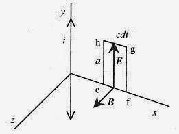
Fig. 43-2
Consider some point along x, an axis oriented radially out from y, the direction of the oscillating current. The oscillating current produces a sinusoidally varying magnetic field at right angles to x and in the plane (x-z) normal to y. Construct the rectangle e-f-g-h with height a and width cdt. This is a “snapshot in space” of the wave passing by the fixed point on x. When the current oscillations start, the oscillating magnetic field progresses in the positive x direction taking a finite amount of time to reach the place where the rectangle is constructed. At the instant of this “snapshot” the leading edge of the wave, as manifest by the B vector, has progressed nearly all of the way through the rectangle.
Now apply Faraday’s law![]() to this rectangle.
to this rectangle.
The differential change in flux over this rectangle is d Φ B = Bacdt, so (d Φ B/dt) = Bac.
Faraday’s law,![]() requires E.dl be integrated around a region where ΦB is changing.
requires E.dl be integrated around a region where ΦB is changing.![]()
In the “Time Varying Magnetic Fields” section of Chapter 37, Faraday’s Law, the area was bounded by a circle. In this situation a rectangle is more convenient. Along e-f and g-h, E is perpendicular to dl and along f-g, E is zero (remember the wave front is passing through the rectangular region), so the only contribution is from h-e. If, as is shown, B is in the positive z direction, E must be in the positive y direction. Positive E along h-e will produce a clockwise current around the rectangle and a magnetic field in the negative z-direction within the rectangle satisfying Lenz’s law. This verifies the relationship of E and B as shown in Fig. 43-2. Integrating counterclockwise around the rectangle, the only contribution to the integral is –Ea. Faraday’s law applied to this rectangle yields
The speed of the wave is the ratio of the oscillating electric and magnetic fields.
43-1 A radio signal at a certain point has a measured maximum electric field of 5.0 × 10 -3V/m. What is the maximum magnetic field?
Solution: The magnetic field maximum is at right angles to the electric field and has magnitude 
<><><><><><><><><><><><>
Now apply Ampere’s law using only the displacement term. ![]()
 Fig. 43-3
Figure 43-3 shows the relationship of E and B. The procedure is much the same as before. The only contribution to the integral is along one side of the rectangle, so the integral becomes Ba (again integrating counterclockwise).
The differential flux is dΦE = Eacdt.
Ampere’s law then is Ba = μoεoEac, or B = μoεoEc.
Substituting E = cB, B = μoεoc2B, so μoεo = 1/c2, or
The velocity of electromagnetic waves (including light) is derivable from static constants!
There are three conclusions to this short discussion.
1. The electric and magnetic fields are related by the velocity; E = cB.
3. The wave moves in a direction determined by E × B.
43-2 How long does it take for an electromagnetic wave to travel to the moon, 3.8 × 10⁸ m away?
<><><><><><><><><><><><>
43-3 How far does light travel in 1.0ns (1.0 × 10⁻⁹ s)?
Energy Transport in Electromagnetic Waves
When electric and magnetic fields are absorbed in material objects, energy is transferred from the wave to the material. This is true for radio waves impinging on antennas, infrared waves absorbed in water molecules, or microwaves into your lunch.
The discussion of energy transport starts with the energy density expressions from static electric and magnetic fields. (See the “Energy Storage” section in Chapter 28, Capacitance, and the “Power and Energy Storage” section in Chapter 38, Inductance.) The total energy density for a region of space where E and B fields are present is 
In the electromagnetic wave E = cB and E2 = c2B2 so B2 = μoεoE2 allowing rewriting  This last expression shows that while the B field is numerically smaller than the E field, the energy density associated with both fields is the same. Referring to Fig. 43-4,
the differential amount of energy in the volume with cross-sectional area A and length cdt is  Fig. 43-4
the expression dU/dt is the energy transported per time over the area A. The more useful expression is the energy flowing across an area per unit of time  The alternative forms come from E = cB and The units of S are energy per unit time per unit area or power per unit area.
The Poynting Vector
The magnitude and direction of the energy flow rate is defined by the Poynting Vector. This vector, like the flow rate, varies with time. The average value of the magnitude of the Poynting vector is the intensity. The average value of the magnitude of S is
 The average value of sin2 ωt is 1/2, so
43-4 Take the intensity of sunlight at the earth’s surface as 600W/m2. Assuming 100% collection efficiency, how much energy is collected on a 1.0m2 panel exposed to this amount of sunlight for 10 hours?
Solution: The key to getting problems involving energy, power, and intensity correct is to watch the units closely. In this case notice how the units dictate how to make the calculation. Another way to do this problem is to find the energy in W.hr rather than Joules.
  This is a strange looking unit, but it gives us a feel for the amount of energy that can be collected this way. This 6000 W.hr would light sixty 100W light bulbs for an hour or run a 1.0kW microwave oven for 6 hours.
<><><><><><><><><><><><>
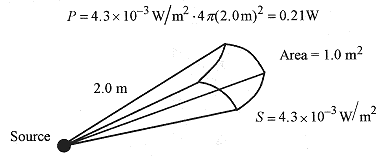
43-5 The maximum value of electric field 2.0m away from a spherically symmetric source is 1.8 V/m. Find the maximum value of magnetic field, average intensity, and power output of the source.
Solution: The magnetic field is from  The average intensity is from
 As an exercise work through the units in this problem.
The total power is the power per unit area at 2.0 m radius times the total area.
Fig. 43-5
<><><><><><><><><><><><>
43-6 What is the maximum electric field strength and intensity of a 500W spherically symmetric light source at 10m radius?
Solution: The area of a sphere 10m in radius is A = 4π(10m)2 = 1.2×10³ m2. The entire 500W is delivered to this area. The power, intensity, and area are related by  The electric field intensity comes from
![]() Radiation Pressure.
Radiation Pressure.
When an electromagnetic wave is absorbed by a material, charges are accelerated by the electric field transverse to the direction of the wave. The electric and magnetic field vectors are shown in Fig. 43-4. The electric field vector is pointing in the +y direction, and this is the direction a positive charge would accelerate. A charge moving in the +y direction acted on by a magnetic field in the +z direction has a (v × B) force in the +x direction, the direction of the wave. The Poynting vector always points in the direction the wave is traveling, so the net force on any charges in the material is in the direction of the wave.
This force can be associated with a momentum. This momentum is![]() This is the momentum absorbed by a non-reflecting surface. For a completely reflecting surface the momentum transfer is twice this value. Think of a tennis ball striking a surface and sticking or striking a surface and rebounding with the incident velocity.
This is the momentum absorbed by a non-reflecting surface. For a completely reflecting surface the momentum transfer is twice this value. Think of a tennis ball striking a surface and sticking or striking a surface and rebounding with the incident velocity.
43-7 A light beam with energy flux 20W/cm2 falls normal onto a completely reflecting surface of 2.0cm2. What is the force on this reflector?
Solution: The average force is F = Δp/Δt and Δp = 2ΔU/c, but ΔU = S AΔt, so


