Magnetic Fields
The magnetic field or B field is a field that produces a force on a moving charge. This is not the only definition, but it is a good operational definition to start with. The force is given by the vector relation![]()
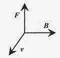
Cross products are discussed in detail in the Introduction, Mathematical Background. In a coordinate system the relation is shown in the accompanying figure.
Fig. 33-1
To fix the direction of the force on a positive charge, place the right hand with fingers pointing in the direction of v, and a line normal to the palm of the hand pointing in the direction of B. Curl the fingers naturally into B. The thumb points in the direction of F. For a negative charge the force is in the opposite direction. The force is a right angles to the plane of v and B.
Since this is a vector it can be expressed as a cross product in determinant form,
or in magnitude and direction form, F = vB sin φ, where φ is the angle between v and B and F points in a direction normal to the plane of v and B as determined by the right-hand rule.
Most problems involve v and B at right angles, so the magnitude of the force reduces to the product of q, v, and B with the direction of F determined by the right-hand rule.
The units of B are (from the force equation 33-1) N.s/C.m or N/A.m, which is called a Tesla (T). The Tesla is related to the smaller and widely used unit the gauss (1 Tesla = 104 gauss).
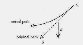
33-1 Calculate the deflection of the electrons in a typical video display tube due to the earth’s magnetic field. Take the electrons with 10KeV energy. Orient the tube north to south and with the electron beam at right angles to the earth’s B field of 0.40 gauss.
Solution: First calculate the velocity of the electrons using an energy relation eV = (1/2)mv2. Convert gauss to Tesla: 0.40 gauss(1T/104 gauss) = 4.0 × 10⁻⁵ T.
Fig. 33-2
Now for the direction. Place the right hand in the direction of v (out of the paper) and curl the fingers into B (down) so the thumb points to the right (looking at the paper). Because this is a negative charge, the force is to the left.
The electron is deflected in a horizontal plane. B in the vertical direction always produces a force in the horizontal plane and at right angles to the velocity causing the electron to move along a circular path. A mass whirled on the end of a string moves in a circle because the (centerdirected) force is at right angles to the velocity throughout the motion.
This last problem is typical of many problems with charged particle trajectories in magnetic fields where the B field is always at right angles to the motion so the vector problem reduces to one of finding the magnitude of the force and then determining the direction via the right-hand rule. This next problem is illustrative of a more difficult problem where the velocity vector has two components. Be sure you have mastered the calculation in problem 33-1, and above all the direction, before moving on to this more difficult problem.
33-2 Take an electron with velocity (components) v = 2.0 × 10⁶ i-3.0 × 10⁶ j m/s and a B field of B = 4.0 × 10⁻³ K T.
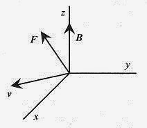
Solution: The force vector in component form is It is a bit hard to envision, but a velocity vector in the x-y plane curled into a B-field vector in the z-direction produces a force vector in the x-y plane. Figure 33-3 shows the orientations.
Fig. 33-3
There are several classic phenomena, experiments, and equipment associated with moving charges in B-fields. These are both interesting and instructive. You will probably use one or more of these instruments in your work.
The Cyclotron
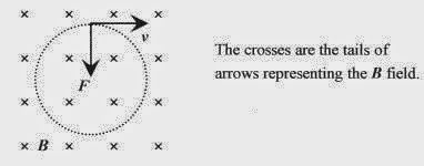
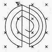
If a particle with negative charge, mass, and velocity is injected into a B field in a plane normal to the field the force is at right angles to the velocity and remains at right angles to the velocity throughout the motion causing the charged particle to go in a circle as shown in Fig. 33-4. A positively charged particle would move in a circle in the opposite direction.
Fig. 33-4
The force is at right angles to the velocity. Apply the v × B law for a negative charge. The magnitude of this force is qvB, and it is always at right angles to the velocity. From mechanics, a motion produced by a force at right angles to the velocity is circular, thus the charged particles move in circular orbits. This qvB force provides the (mechanical force)mv2/r, so equating these forces![]()
There are several relations that follow from this statement, but for the cyclotron the most important is one for the orbit radius![]()
and the one for the angular frequency ![]()
33-3 An electron of energy 4.0 KeV is circulating in a plane at right angles to a magnetic field of 3.0T. What is the radius of the orbit?
Solution: The geometry is the same as in Fig. 33-4. First, calculate the velocity from the energy.![]()
33-4 An α-particle moves in a circle of radius 5.0 × 10⁻² m in a magnetic field of 2.0 T. Find the speed of the α– particle and the frequency and period of the motion.
Solution: An α-particle is a helium nucleus, which has two protons and two neutrons. The speed of the α– particle is from the defining equation for the cyclotron. 
The angular velocity is (analogous to mechanics) 
The frequency, or what is called the cyclotron frequency, is f = w/2π = 1.5× 10⁷ 1/s.
The period, or time for one transit of the circle is T = 1/f = 6.7 × 10⁻⁸ s.
<><><><><><><><><><><><>
A cyclotron is a device for accelerating charged particles while they are being forced to travel in a circular path by a magnetic field. A source of, say, deuterons is placed at the center of the device. A deuteron is a proton and neutron combination with one electronic charge and 2 amu. An amu (atomic mass unit) is the average mass of a nuclear resident (neutron or proton). The deuterons exit the source with a small velocity to the right. The radius of the circular orbit is given by r = mv/qB and is quite small. The particle enters a semicircular open area between “D” shaped plates and travels in a circular orbit until it exits the “D” area. The voltage between the Dees, as they are called, is alternated sinusoidally so that on leaving the right Dee the particle is accelerated and assumes a new (larger) orbit in the left Dee. When the particle leaves the left Dee the voltage is again switched so that acceleration is accomplished across the Dees. Remember that the angular frequency is qB/m, and is not dependent on velocity!
Fig. 33-5
33-5 Calculate the frequency of oscillation of the Dee voltage for a deuteron in a 2.0T magnetic field.
<><><><><><><><><><><><>
33-6 What is the maximum energy of a deuteron in this cyclotron with maximum available radius of 1.5m?
Solution: The kinetic energy is (1/2) mv2, but v can be written in terms of the r, q, B, and m according to the basic equation defining the cyclotron orbits. 
The deuteron gained this large amount of energy by making many traverses of the distance between the Dees as the voltage was alternating at the cyclotron frequency.
The Mass Spectrometer
Another application of the circular orbits in a magnetic field is in the mass spectrometer. Ionized atoms are injected into a magnetic field at a known energy (velocity). They take up circular orbits with radii determined by their mass. The ions are detected with a photographic plate or traveling collector.
The ions are accelerated (by a voltage) to a particular energy before they enter the magnetic field region. Their energy is their charge times this accelerating voltage. This is the energy the ions have while orbiting in the magnetic field. (See the previous problem.)
Fig. 33-6
The ions strike the photographic plate a diameter x = 2r from the injection point, so ![]()
33-7 Calculate the mass of a singly charged ion accelerated through 4120V and striking the collection area at 7.0 × 10⁻² m from the entrance point in a 1.0T field.
Solution:  The ion is carbon 14, an isotope of carbon 12.
<><><><><><><><><><><><>
Another function of this type of mass spectrometer is to separate out isotopes, atoms with the same nuclear charge and number of electrons but with different nuclear mass. The sensitivity of the spectrometer can be found by looking at the variation of x with m. Start with![]()
The sensitivity is measured by the ratio of Δm tom.
33-8 Calculate the resolution required of the photographic plate to differentiate between carbon 12 and carbon 14.
Solution: Use the diameter from the previous problem, 7.0 × 10⁻² m, and m as 12 amu with Δm as 2 amu. 
This value is easily obtained on a photographic plate.
The J. J. Thomson Experiment
The J. J. Thomson experiment uses crossed electric and magnetic fields to measure the charge to mass ratio for the electron. This was a classic turn-of-the-century experiment.
Fig. 33-7
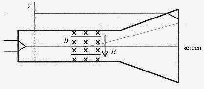
The force equation for moving electrons subject to both electric and magnetic fields is![]() The electric and magnetic fields are arranged as shown. Verify that a negatively charged particle will experience a “down” force due to the magnetic field and an “up” force due to the electric field. In the tube, the voltage V accelerates the electrons from the hot filament and the electrons enter a field-free region between the accelerating grid, shown as the dotted line, and the video screen.
The electric and magnetic fields are arranged as shown. Verify that a negatively charged particle will experience a “down” force due to the magnetic field and an “up” force due to the electric field. In the tube, the voltage V accelerates the electrons from the hot filament and the electrons enter a field-free region between the accelerating grid, shown as the dotted line, and the video screen.
In the experiment, a deflecting electric field is applied and the spot on the screen is observed to move up on the screen. The B field is added to bring the spot back to zero deflection. In this situation the net force is zero and because of the directions of E, v, and B, E = vB.
33-9 An electric field of 1.0 × 10³ V/m and a magnetic field of 0.35T act on a stream of electrons so as to produce zero net force. What is the speed of the electrons?
<><><><><><><><><><><><>
The velocity of the electrons is determined by the accelerating voltage in the tube. The electrons are accelerated before they enter the region of crossed E and B fields and travel through this region and to the screen without further acceleration axially down the tube. The kinetic energy of these electrons is eV, the electronic charge times the accelerating voltage. For zero deflection an energy statement can be made replacing v with E/B.
The charge to mass ratio for the electron can be determined by the applied voltage and fields in the tube.
33-10 Calculate the charge to mass ratio for charged particles in a J. J. Thomson tube with accelerating voltage of 3000V and crossed fields of E = 6.5 × 10⁴ V/m and B = 2.0 × 10⁻³T.
Solution:  Verify that this is the correct charge to mass ratio for electrons.
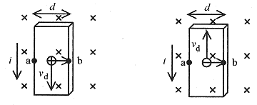
The Hall Effect. The Hall effect is used to determine the algebraic sign and number density, n, of charge carriers in a conductor. Set up a slab of unknown material in a magnetic field as shown. In one sample (left
Fig.33-8
side of Fig. 33-8) assume the current is due to charge carriers that are positive, and, in the other, negative. Apply the v × B force on each, with the B field directed into the page, and notice that despite the sign of the carriers they will be deflected to the right. This accumulation of carriers will create a “transverse” or Hall voltage, which has a different direction depending on the sign of the charge carriers. In the sample on the left (positive charge carriers) point b is at a higher potential than point a. In the sample on the right (negative charge carriers) point b is at a lower potential than point a. The sign of the voltage produced in the Hall experiment gives the sign of the charge carriers. Charges build up to produce an electric field (the transverse Hall field) that just balances the magnetic force on the charge carriers.
This Hall field is EH = VHd.
The Hall field is also the E in the statement for zero force, 0 = qE + qv × B.
This produces a Hall field of EH = vdB.
The current density in the sample is j = nevd.
Combining,![]() from which the charge carrier density is
from which the charge carrier density is 
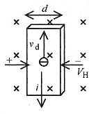
33-11 In a Hall experiment the current is 2.0 × 10⁻³ A when 2.0V is applied to a semiconductor of length 6.0cm, width 3.0cm, and depth 0.20cm. A magnetic field of 2.0 T produces a Hall voltage of 2.0×10⁻⁴ V. Find the sign of the charge carriers, their number density, and the resistivity of the material.
Fig. 33-9
Solution: The sign of the Hall voltage indicates negative charge carriers. Now calculate the current density.  The Hall field is EH = VH/d = 2.0 × 10⁻⁴ V/3.0 × 10-2 m = 6.7 × 10⁻³ V/m.
The number density of charge carriers is  The resistivity of the sample is easily calculated from the defining statement E=ρj and remember that this E is not the Hall field but the field driving the current through the sample.
 ![]() These measurements of the sign of the charge carriers, their number density, and the resistivity are very important in the characterization of semiconductor material.
These measurements of the sign of the charge carriers, their number density, and the resistivity are very important in the characterization of semiconductor material.

