Capacitance
A capacitor is a geometric arrangement of conducting plates where charge can be stored. The capacitance is ameasure of the charge that can be stored per volt. The unit of capacitance, the farad, is defined as a Coulomb/Volt. The defining equation
for capacitance is C =q/V.
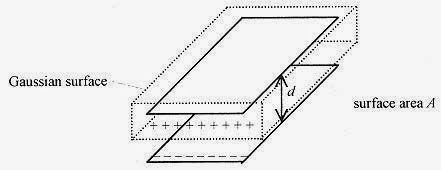
The simplest capacitor is two parallel plates of area A and separation d.
Fig. 28-1
The capacitance of a parallel plate capacitor determines the amount of charge that can be stored on the plates. A battery connected to the plates will place charge on the plates. For this discussion the battery can be viewed as as ource of charge (or charge pump) with the amount of charge delivered to the plates determined by the voltage of the battery. Remember that the voltage of the battery is a measure of the amount of work that can be performed on a unit of charge.
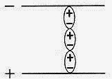
When the battery is connected to the plates, we say that positive charge begins to flow onto the positive plate and negative charge onto the negative plate. The first “piece of charge” distributes uniformly over the plate. The positive and negative charges arrange themselves on the plates opposite one another. As more charge is pumpedonto the plates the work necessary to place each new “piece of charge” on the plate increases because of themutual repulsion of the charges already on the plate. Thus the capacity of the device to store charge is directlyproportional to the plate area.
The limitation on capacity imposed by the mutual repulsion of like charges on one plate is offset by oppositecharges on the other plate. As the distance between the plates is reduced, the attraction between unlike chargesmakes it easier, in terms of work performed by the battery, to place charge on the plates and the capacity of thedevice is increased. Thus capacitance is inversely proportional to the separation of the plates.
The capacitance of a parallel plate capacitor is directly proportional to the plate area and inversely proportionalto the separation, with a constant added to make the units work out correctly.![]()
This very simple view of a parallel plate capacitor produces the correct functional relationship as seen in theformal derivation in the following paragraph.
The formal procedure for determining capacitance is to:
1) calculate E using Gauss’ law, then
and finally
3) calculate C from the definition![]()
For the parallel plate capacitor, charge the plates with a battery so that one plate contains positive charge andthe other negative charge. The charges will arrange themselves so they are on the insides of the plates oppositeone other (unlike charges attract). Construct a Gaussian surface surrounding one plate. The E-field exists onlybetween the plates and is constant over the Gaussian surface. Applying Gauss’ law![]()
E is a constant over the Gaussian surface so the integral ofE over this surface is just E times A, the surface area.This is another case of an integral that can be evaluated by looking at it and writing down the answer. In this mgeometry the relationship between voltage and field is simple, V=Ed, so εoVA/d =q and the capacitance, whichis defined as ![]() m
m
The capacitance is entirely geometry dependent. One thing to notice here is εo, which can be expressed in thenew units of Farad/meter or F/m.
28-1 A capacitor with circular plates of 0.20m radius separated by 0.0010m is connected to a 100V battery.After a long time the battery is disconnected. What is the charge stored on the plates?
Solution: The capacitance of the arrangement is![]()
The charge is obtained from the definition of capacitance, equation 28-1
<><><><><><><><><><><><>
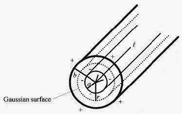
28-2 Calculate the capacitance of a cylindrical capacitor of inner radius a, outer radius b, and length l.
Solution: Set up a cylindrical Gaussian surface symmetrical about the inner cylinder and of length l.
Fig. 28-2
E is constant over this surface and ![]()
Continuing with the procedure, calculate V.![]()
<><><><><><><><><><><><>
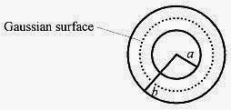
28-3 Calculate the capacitance of a spherical capacitor with inner radius a and outer radius b.
Solution: Set up the Gaussian surface symmetric about the inner sphere. E is a constant over this surface and![]()
Capacitors as Lumped Circuit Elements.
Capacitors are used in electric circuits, so it is necessary to know how capacitors add when used in series andparallel. First look at three capacitors placed in series.
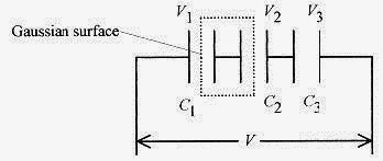
Fig.28-4
The applied voltage is distributed between the three capacitors so V=V1+V2+V3. Since there is no way to addcharge except to the end plates, those connected directly to the battery, then the charge contained within theGaussian surface must total zero.
The right plate of C1 has equal but opposite charge to the left plate of C2. Another Gaussian surface surroundingC1 also must have total charge zero, so the charge on the plates of C1 are equal and opposite. Proceeding in thismanner the magnitude of the charge on all the plates is the same. Rewriting the equation for the voltage usingthe definition of capacitance
Therefore ![]() can be replaced by an equivalent capacitance
can be replaced by an equivalent capacitance![]()
Capacitors placed in series add in a reciprocal manner.![]()
Capacitors placed in parallel add linearly. Look at the expression for C for a parallel plate capacitor: C = εoA/d.Adding another parallel capacitor just adds more εoA/d to the capacitor. Therefore, capacitors placed in paralleladd linearly.![]()
28-4 A 6.0 μF capacitor and an 8.0 μF capacitor are connected in series. A potential of 200V is placed acrossthem. Find the charge and potential on each.
Fig. 28-5
Solution: The circuit is as shown. Since the capacitors are in series the charge on each capacitor is the same.The equivalent capacitance is found from
so the equivalent capacitance is (24/7) μF, and the equivalent circuit is as shown.
The charge is easily calculated from q = CV = (24/7) μF. 200 V = 686 μC. The voltage on each capacitor is
These voltages add to the 200V applied to the combination.
<><><><><><><><><><><><>
NOTE: This general approach of reducing circuits to simpler equivalents by applying the rules for lumped circuit elements is at the heart of circuit analysis.
28-5 A 12 μF capacitor and a 10 μF capacitor are connected in parallel across a 100V battery. Find the charge and potential on each capacitor
.Fig. 28-6
Solution: The circuit is as shown. The voltage across each capacitor is the same, 100 V. The charge, however,depends on the capacitance.![]()
Look at the equivalence. Take this total charge and the applied voltage and find an equivalent capacitance.![]()
This is the sum of the capacitances as expected in a parallel arrangement.
28-6 The analysis of multiple capacitor combinations is done with (sometimes several) equivalent circuits.Consider the circuit shown that has parallel and series combinations.
Fig. 28-7
Solution: The first equivalent circuit comes from the combination of C1 and C2.
Now combine C3 and C4 to C5=C3+C4 =4.4 μ F + 6.0 μ F = 10.4 μ Fallowing construction of the final (simplest)equivalent circuit
Fig. 28-8
Now calculate the total charge q t = C5V = 10.4 μ F.300 V=3.1 × 10⁻³ C.
The charge on C3 is q3 =C3V = 6.0μF.300 V= 1.8 × 10⁻³ C.
The remaining charge is 1.3 ×10⁻³ C, and this is the charge on each of the other capacitors, C1 and C2. Rememberthat the charge on capacitors in series is the same. The voltage on each of these capacitors is
The error here of these voltages not adding up to 300V is about 2%, which is expected from round off.
28-7 Charge a 12μF capacitor with a 200V source, then place this capacitor in parallel with an uncharged 7.0μFcapacitor and calculate the “new” voltage.
Fig. 28-9
Solution: The 12 μ F capacitor initially placed on the 200V source has a charge of ![]()
When connected to the 7.0μF capacitor the charge distributes so that the total charge remains the same and the“new” voltages are equal as they must be for capacitors in parallel. Take Q as the amount of charge that moves from the 12μF capacitor to the 7.0μF capacitor. The voltages as expressed by the ratio of q to C must be equal,so write ![]()
The voltage on each of the capacitors is ![]()
Energy Storage
If the potential of a capacitor is defined as the work required to move an amount of charge from one plate to theother, then in differential form ![]()
and the integral of this expression to find the total work to move an amount of charge q is
This work is equal to the energy stored in the capacitor, U. Another quantity of interest is the energy that can bestored per unit volume. For a parallel plate capacitor, where C = εoA/d
28-8 Go back to the previous problem of the 12μF capacitor charged to 200V and then connected to the 7.0μFcapacitor and look at the question of energy
Solution: The 12μF capacitor at 200V has a stored energy of![]()
NOTE: The units of energy are [FV2]=[(C/V)(J/C)2]=[J].
After the capacitors are connected, the voltage drops to 126V and the energy stored in the two capacitors is
Where did the energy go? The difference between the 0.24J and the 0.15J is the kinetic energy needed totransport the charge or the work to move the charge.
Capacitors and DielectricsDielectrics
are most conveniently thought of as materials containing dipoles that are “loose” and can line upwith an applied electric field. The easiest way to understand dielectrics is to approach them experimentally.Using a parallel plate capacitor as a model observe experimentally that the amount of charge per unit voltageincreases with the insertion of various dielectric materials. The easiest way to explain this is t
osay that C = εoA/d is changed by a factor kgr;, so C = κεoA/d with this κ called the dielectric constant, ameasure of the amount by which the capacity of a capacitor is increased due to a particular dielectric.T
he mechanism of increasing the capacitance can be thought of as the dipoles lining up across the separation dwith the positive end of the string effectively neutralizing some of the negative charge on the plate and the negative end of the string doing the same to the other plate. The effect of these positive charges in the vicinity of the negative plate allows the negative plate to be negatively charged more easily (with less work) leading to agreater capacity of the device in the presence of the dielectric.
Fig. 28-10
Consider another experiment with dielectrics. Connect a battery in parallel with identical sized parallel platecapacitors except one has a dielectric and the other does not. For the one without the dielectric C = εoA/d. Andfor the one with the dielectric C=κεoA/d. Since q=CV, to carry the same charge the capacitor with the dielectricwould have to have V reduced to Vo/κ and likewise E to Eo/κ. Finally looking at the energy density forcapacitors with dielectrics
28-9 A parallel plate capacitor of 2.0 × 10⁻⁹ F and plate area 0.50 m2 is connected to 3000V. Calculate the storedenergy.
<><><><><><><><><><><><>
28-10 The plates (problem 28-8) are physically pulled apart to double the original separation. Calculate the work performed by the outside agent pulling the plates apart, the average force exerted on the plates, and the average power if the separation occurs over 10s.
Solution: First, calculate the original separation from
Substituting the expression for the capacitance of a parallel plate capacitor the total energy is ![]()
If the separation is doubled the energy is halved. The energy density is reduced by one-quarter. (Refer to equation 28-9.) In this case the energy is reduced from 90 ×10-4 J to 45 × 10-4 J. This 45×10-4 J energy loss must be the amount of work done in separating the plates. The work is force times distance, so the average force would be![]()
If this work were done over 10 seconds the power would be

