Simple Gates-NOT, AND and OR
The circuits of a computer may contain millions of components, but most of this is made up by repeating a few different gates.
NOT GATE (INVERTER)
(The output is NOT the same as the input.)
Functions of NOT gate in words: a logic gate with one input. The output is logic 0 if the input is logic 1 and is logic 1 if the input is logic 0.
Truth table for NOT gate
|
Input |
Output |
|
0 |
1 |
|
1 |
0 |
Fig 3 Truth table for a NOT gate
Note: The operation carried out by a NOT gate is referred to as inverting.
AND GATE
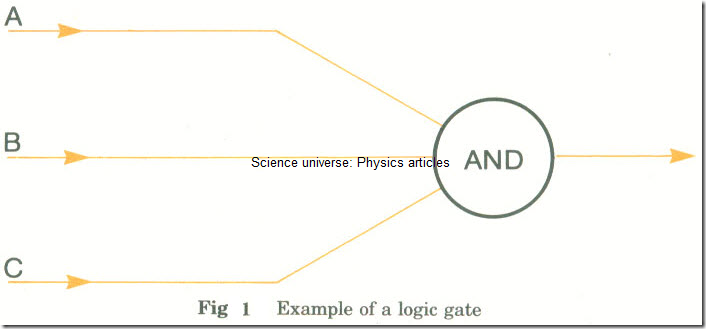
(The output is 1 only when A AND B are 1)
Functions of AND gate in words: a logic gate with two or more inputs. The output is logic 1 when both (or all) the inputs are logic 1; otherwise the output is logic 0.
Truth table for AND gate (two inputs)
|
Input |
Input |
Output |
|
A |
B |
|
|
0 |
0 |
0 |
|
0 |
1 |
0 |
|
1 |
0 |
0 |
|
1 |
1 |
1 |
Fig 4 Truth table for an AND gate
OR GATE
(Output is 1 when A OR B is 1-this includes the case when both of A and Bare 1.)
Function of OR gate in words: a logic gate with two or more inputs. The output is logic 1 when anyone of the inputs is logic 1; the output is logic 0 when both (or all) the inputs are logic 0.
Truth table for OR gate (two inputs)
|
Input |
Input |
Output |
|
A |
B |
|
|
0 |
0 |
0 |
|
0 |
1 |
1 |
|
1 |
0 |
1 |
|
1 |
1 |
1 |
Fig 5 Truth table for an OR gate
Worked questions
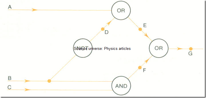
1 Draw a truth table for the following logic diagram. Show the logic values at D, E, F and G.
Answer: The truth table is as follows:
|
A |
B |
C |
D |
E |
P |
G |
|
0 |
0 |
0 |
1 |
1 |
0 |
1 |
|
0 |
0 |
1 |
1 |
1 |
0 |
1 |
|
0 |
1 |
0 |
0 |
0 |
0 |
0 |
|
0 |
1 |
1 |
0 |
0 |
1 |
1 |
|
1 |
0 |
0 |
1 |
1 |
0 |
1 |
|
1 |
0 |
1 |
1 |
1 |
0 |
1 |
|
1 |
1 |
0 |
0 |
1 |
0 |
1 |
|
1 |
1 |
1 |
0 |
1 |
1 |
1 |
Notes: 1 A,B,C, are the inputs. The table must show all eight combinations of these.
2 D is obtained by inverting values of B.
E is obtained from the A and D columns using the truth table for OR.
F is obtained from the B and C columns using the truth table for AND.
G is obtained from the E and F columns using the truth table for OR.
2 If A = 10011, B = 10101 and C = 11001 find (A OR B) AND (NOT C), carrying out the operations on corresponding bits of A, B and C.
Answer: A OR B= 10111
NOT C=00110
∴ (A OR B) AND (NOT CI=10111 AND 00110 =00110
Note: Detail of A OR B: 10011
10101
10111
The bits are OR-ed one pair at a time-a bit from A with a bit from B.
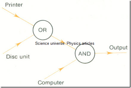
3 A line to a computer is to be in use when a printer or a disc unit are free and when the computer is also free. Draw a logic diagram for a circuit which will ensure that this is so.
Assume that when a device is free it inputs 1 to the circuit, and 0 when it is not free. Assume when the circuit outputs 1 the line is in use.
Answer: The circuit is:
4 Draw a truth table for the following circuit:
Answer; The truth table is as follows:
|
A |
B |
c |
NOTB |
Output |
|
0 |
0 |
0 |
1 |
0 |
|
0 |
0 |
1 |
1 |
0 |
|
0 |
1 |
0 |
0 |
0 |
|
0 |
1 |
1 |
0 |
0 |
|
1 |
0 |
0 |
1 |
0 |
|
1 |
0 |
1 |
1 |
1 |
|
1 |
1 |
0 |
0 |
0 |
|
1 |
1 |
1 |
0 |
0 |


