The V-Curve of a Synchronous Generator
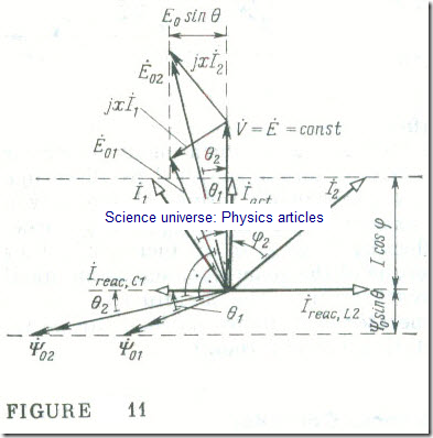
A valuable property of a synchronous generator operating into a large power system is that its reactive current can be controlled by varying its excitation current. For a better understanding of the matter, let us turn to the phase phasor diagram of a synchronous generator (see Fig 8) and analyse it from this point of view (Fig 11) . If the power developed by a synchronous generator, P = ɷrotTem, and the voltage across the system busbars, V, are constant, then the products of the terms in Eq. (15.10)
I cos φ = Iact = const (15.14)
E0 sin │θ│ = ɷ Ψ0 sin │θ│ =const
are independent of the excitation current. However, a change in the excitation current brings about a change in the associated flux linkage with the stator phase winding, Ψ̇0 , and in the emf Ė0 induced by this flux linkage in the phase winding.
It follows from the equation of- electric state of a stator phase, Eq. (15.8), that this can happen only if there is a proportionate change in the phase current
İ= İact + İreac
or, to be more exact, in the reactive current, İreac .
When the excitation current is less than some limiting value,
If < If,Ifm (P), the current in a capacitive reactive component, Ireae,c . When the excitation current is greater than some limiting value, If > If,1fm, the current in a synchronous generator contains an inductive reactive component, Ireae,L (Fig. 11). The phase angle respectively is φ < 0 and φ > 0 . In consequence, underexcitation makes the reactive power of a synchronous generator capacitive in its effect,
QC = 3VIreac,c
and overexcitation makes it inductive in its effect
QL = 3VIreac,L
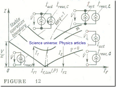
If a synchronous generator operates into a large power system with V = const, its equivalent circuit may be drawn up as a parallel combination of two current sources, one being a source of active current which depends on the torque developed by the prime mover, Iact = f (Tpm), and the other being a source of reactive current which depends on the torque developed by the prime mover and the excitation current, Ireac = f (If, Tpm).
In the special case of a zero prime-mover torque, Tpm = 0, the phase equivalent circuit of a synchronous generator operating into a large system will contain no active current source, and the reactive current will be solely dependent on the excitation current,
Ireac = f (If)·
The plots of the current of a synchronous machine operating into a large power system with V = const, as a function of the excitation (field) current, I = f (If), at a constant prime-mover torque; Tpm = const, are called the V-curves of the machine (Fig. 12) . At some low value of excitation current the angle │θ│(see Fig 10) may exceed π/2 in value, and the stability of the machine may be upset. The greater the active power of a synchronous generator, the greater the excitation current at hich the machine may lose its stability. In Fig 12 the boundary of stable operation for a synchronous generator is shown by a dashed line .
The torque developed by the prime mover is zero, Tpm = 0, then, on neglecting all forms of loss, we may take it that the current in a synchronous generator is purely reactive (see Fig 12, P = 0) :
İ (If) = İreac (If) = (Ė – V̇)/j = (jɷΨ̇0 (If) – V̇)/j (15.15)
Now the generator current is a linear function of the excitation current. The function I = f (If) ceases to be linear only at high values of excitation current owing to the saturation of the magnetic circuit of the machine.


