The Selection of Power Rating for a Drive Motor
The primary considerations in the selection of the power rating for a drive motor are economy, efficiency, and reliability. The use of an overrated motor would entail a waste of power, unwarranted capital outlays, and an increase in the required floor area. An underrated motor would reduce the efficiency of the driven machine, impair overall reliability, and might be readily damaged.
A drive motor must be chosen so that its power output is utilized to the best advantage. In operation, it should be heated to about the maximum safe temperature, but never exceed it. Also a drive motor should give normal performance in the case of likely short-time overloads and develop the starting torque required by the driven machine. Accordingly, the power rating of a drive motor is mostly chosen with regard to heat capacity (or temperature rise), following which a check is run to see if the motor thus chosen has an overload capacity sufficient to meet the expected starting conditions and to sustain short-time overloads. Sometimes (when the short-time load is very large), a drive motor would be chosen to meet the maximum power requirements. In such a case, it often happens that the continuous-duty power of the motor is not fully utilized.
The selection of the power rating for a drive motor to be used in continuous duty is the simplest of all. In the circumstances the power output of the motor should be equal to the load power, and no check needs to be made for heat capacity and overload under running conditions. However it is important to see if the motor thus chosen can develop sufficient torque at starting in order to start the load satisfactorily under the most severe starting conditions that may be encountered in that particular application.
For a wide range of traditional loads the power requirements are determined on the basis of theoretical calculations that have stood the test of practice. For example, for a fan the power rating of its drive motor, in kW, must be
p = ν Δp/1000ηfanηtrans
where ν is the quantity of air handled by the fan, m3s-1Δp; is the pressure differential , Pa; ηfan is the efficiency of the fan (for propeller fans tile figure is 0.2-0.35 and for centrifugal fans it is up to 0.8); and t]trans is the efficiency of the transmission from motor to fan.
In the above equation the product ν Δp is the useful power output of the fan, and 1000 is a factor used to convert power to kilowatts.
In many cases the power rating of a drive motor for use in continuous duty is found by empirical formulas tested in many years’ practice.
For poorly explored applications the continuous-duty rating of a drive motor is determined by measuring specific energy consumption in actual service or by putting the drive to a trial operation.
The selection of the power rating for drive motors to be used in short-time and intermittent duty. In any class of duty it is important to know how the temperature rise, ϑ, of the drive motor varies with time. From the view-point of heat build-up an electric machine is an extremely heterogeneous body. Yet, in cases which do not call for an especially high accuracy it is legitimate to treat an electric machine as a homogeneous body.
Accordingly, we may use the following simplified equation of heat build-up:
Q0 dt = C d ϑ + H ϑ dt (16.10)
where C is the heat capacity of the machine, H is its heat transfer, and Q0 is the heat generated within the machine per unit time.
At t tending to infinity,
Q0 dt = H ϑ max dt
and
ϑ max = Q0IH
Hence,
ϑ max dt = (C/H) d ϑ + ϑ dt
On solving the above equation by separation of variables, we get
A exp (-t/τ) = ϑ max – ϑ
Where τ = C/H is the time constant of heat build-up found by experiment.
At t = 0, the initial temperature rise is
ϑ = ϑ0
so that
A = ϑmax – ϑ0
and the temperature rise of the machine can be written as
ϑ = ϑmax – (ϑ max – ϑ0) exp (-t/τ) (1611)
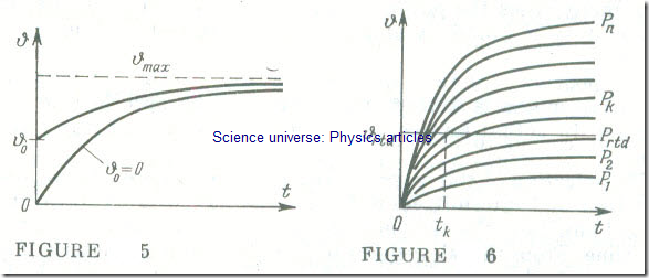
That is, in the above case the temperature rise will increase exponentially, tending to ϑmax. in much the same way as it does when ϑ0 = 0 .
The value of the initial temperature rise only varies the rate of temperature change, but does not affect the nature of the process (Fig 5).
Given various values of continuous-duty load, the plots of ϑ as a function of time of one and the same machine will only differ in ordinates (Fig 6). The maximum safe temperature rise for a given machine is ϑrtd, shown by a line, ϑ = ϑrtd, parallel to the axis of abscissae. It intersects the ϑ = f (t) curves at various points corresponding to various loads sustained by the motor. The abscissa of the intersection defines the time interval, tk, during which the power delivered by the motor may temporarily be equal to Pk representing the overload over its continuous-duty power rating. The temperature-rise curve asymptotically approaching ϑrtd corresponds to the power rating, Prtd . of the motor. At loads less than Prtd . the power of the motor is not utilized fully. This also goes for cases where a motor is loaded to its rated power for a relatively short time.
In fact, it is advisable to overload a motor for a short time, with the overload being progressively increased as the duration of overload ‘ is decreased. The limit to which the overload may be increased as the duration of a load period is decreased is determined by the instantaneous overload capacity of the motor which in turn depends on its electric parameters (the maximum torque in the case of induction motors and the commutation conditions in the case of d.c. machines).
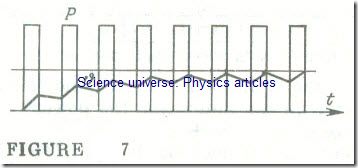
In intermittent duty, a drive motor alternatively builds up and dissipates heat. Variations in its temperature during each cycle depend on its heat balance during the previous cycle. A plot of heat build-up and cooling as a function of time for an intermittent-duty motor is shown in Fig 7. The final temperature rise in a given part of the cycle is the initial temperature rise for the next part of the cycle. In the case of a marked change in the cooling conditions during a particular part of a cycle (the motor is stopped or its speed is changed substantially), this will cause achange in τ = C/H, the time constant of heat build-up, and this change must be reflected in the construction of the plot.
The selection of a power rating on the basis of temperature rise and heat build-up plots (or through the use of an applicable analytical approach) is very time-consuming and does not yield accurate results. We have included the above graphs only in order to illustrate how the temperature of a motor varies with changes in its load. In most cases, power requirements are determined by simpler methods, notably by the equivalent current method .
The equivalent current method is based on the assumption that the average losses of a motor carrying a variable load should be equal to the losses occurring in the case of continuous (rated) load. As has he en noted more than once, the losses of a motor are the sum of the fixed (or constant) losses, Pflxed, and the variable loss, Pvar. The fixed losses include windage and friction losses, core losses (in the case of induction and shunt-wound d.c. motors), and excitation losses (in the case of synchronous and shunt-wound motors). The fixed losses may be taken to be proportional to the square of the running current I of the motor and the resistance r of the corresponding winding, of which the latter may be assumed to be constant. If the current changes during some time intervals, then the overall loss of power in a motor in the time Σ t = T will be
(Pfixed + rI21) tl + (Pfixed + rI22) t2 + …
+ (Pfixed + rI2k) tk + … + (Pfixed + rI)tn
Assuming an equivalent load current, Ieq , the power lost in a motor over the same time T would be
(Pfixed + rI2eq) T
In either case the same amount of power must be dissipated as heat. Hence the equivalent current may be defined as
Once we know the equivalent current, the rated voltage and the rated power factor, we can determine the power rating of the motor Prtd ≥ VrtdIeq cos φrtd ·
The equivalent-current method is applicable only if the core loss, the windage and friction losses, and the winding resistances remain constant through the total operating time. This requirement will not, for example, be satisfied by a series-wound motor in which a change in load brings about marked variations in the flux and speed (and, in consequence, variations in the core loss and windage and friction losses).
In some applications it is necessary to determine the required torque directly, rather than current. This is done by the use of the equivalent-torque method: in all electric motors the torque is proportional to the product of the current and flux. For a.c. motors, the power factor may be assumed to be approximately constant. By the same token, the magnetic flux may be deemed constant in all motors except series-wound and compound motors. Under the above simplifying assumptions we may define the torque as
T = kI
where k is a constant. Then, on the basis of Eq. (16.12), it follows that
Knowing the equivalent torque and the rated angular velocity ɷrtd, we can readily find the power rating of the motor
Prtd = Teqɷrtd
After the power rating of a motor has been selected by the equivalent-current or equivalent-torque method it is important to verify that the maximum torque Tmax of the motor is sufficient to meet the short-time overload requirements in a particular application. In other words, the designer should check to see that the following requirement is satisfied: The overload factor A.rtd must be greater than the ratio of the maximum load torque Tmax to the rated motor torque, that is,
λrtd > T max /T rtd


