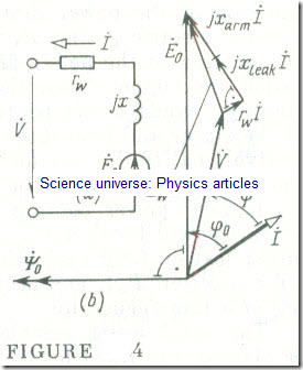
The Equivalent Circuit and a Simplified Phasor Diagram for a Phase of a Synchronous Generator
The equivalent circuit answering the equation of electric slate of a stator phase of a synchronous generator is shown in Fig 4 a. Now we will construct a phasor diagram for a phase of a synchronous generator. To do this, we choose as reference the main flux linkage vector Ψ̇0 which is directed to the left along the axis of abscissae .
(Fig 4 b). The phasor of Ė0 induced by Ψ̇0 is in quadrature lagging with Ψ̇0 .The phasor of the stator (armature) current İ is lagging £0 by an angle φ0 determined by the relative magnitudes of the reactances and resistances
φ0 = arc tan ( + load)/(rw + rload) (15.4)
where load and rload are the reactance and resistance of the generator load.
The phasor of voltage rw İ is aligned with the current phasor İ , and the voltage phasor jİ is in quadrature leading with it. The phasor of the terminal voltage per phase V̇, can be located by subtracting the sum of the voltage phasors across the resistance and reactance per phase from E0 :
V̇ = Ė0 – jİ – rw İ
On joining the tips of the phasors E0 and V̇ , we obtain a triangle of voltages across the resistance and inductive reactance per phase , with Zw İ as hypotenuse.
The phasor rw İ is shown on an exaggerated scale to make the diagram more instructive.

