The Equation of Motion for a Motor Drive
In designing a motor drive, one has to know the mechanical arrangement, horsepower and torque requirements, and special conditions of operation of the driven machine. All of these- factors will determine, in one way or another, the static and dynamic loads applied to the shaft of the drive motor.
Static load refers to that arising from friction, the force(s) exerted in machining a component, the self-weight of the motor and driven machine, and the like. Dynamic load arises from variations in the kinetic energy of the drive system in tho wake of changes in the speed of its various parts or members. Accordingly, the torque developed by the drive motor may be defined as
Tmot = Tst + Tdyn ( 16.1)
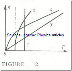
Here Tst is the static torque due to all opposing forces. It may not depend on speed (curve 1 in Fig 2) if it is due to friction, the opposing force which results from machining a metal part, and the like, or it may depend on rotational speed to some extent.
In the case of a centrifugal pump, for example, feeding a con taut-head system, the static torque has a constant component and a component proportional to the square of T rotational speed (curve 2 in Fig 2). This dependence on speed may be linear (curve 3) or nonlinear (curve 4) .
The second term, T dyn , is the dynamic torque defined as Tdyn= J dɷ/dt . It may be positive or negative. It is proportional to J, the moment of inertia. For a rotating solid body the moment of inertia with respect to a given axis of rotation is the limit of the sum of the products of the masses mk of each of the elementary particles into which the body may be conceived to be divided and the square of their distance, Riner from the given axis of rotation
Usually it is convenient to express the moment of inertia as the product of the mass of the body by the square of the radius of inertia, also called the radius of gyration , Riner , that is
where Riner is the distance from the axis of rotation at which all the mass of the body must be concentrated in order to obtain a moment of inertia equal to the actual one when the mass is distributed. The radii of inertia (radii of gyration) for simple solid bodies are given in reference tables.
In the solution of problems dealing with rotating bodies, notably drives, it was customary at one time to use the concept of flywheel effect to which the moment of inertia of a solid body is connected by a simple relation of the form
J = GD2/4g (16.4)
where G is the weight of the body, D = 2Riner is the diameter of inertia (diameter of gyration), g is the acceleration due to gravity, and GD2 is the flywheel effect.
The moments of inertia for the rotors and armatures of electric motors are usually given in data sheets.
The best proposition would be to connect a drive motor to the driven device (say, the cutter of a machine-tool) directly, avoiding the use of any intermediate gearing or belting. In most cases, however, this cannot be done because the tool has to be driven at a relatively low speed (50-300 rpm), whereas the available motor is a high-speed type. It would not pay to design and build a special purpose low-speed motor as it would be too large and too heavy. An optimum decision is to connect a normal motor (with a speed of 750-3000 rpm) to the driven tool via a step-down gearbox.
In the solution of problems dealing with driven machinery incorporating elements which execute rotational or translational motions at different speeds it is advantageous to replace the actual system with what may be called a reduced system, that is, a simplified one which consists of an only member driven at the speed of the drive motor. In replacing an actual system with a reduced one, an important step is to re-scale all the torques in such a way that the power (or energy) relations remain unaffected.
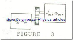
Suppose there is a drive motor rotating at wmot. which is coupled via a single-step gear transmission to a machine tool whose angular velocity is wm.t (Fig 3, in which Jmɷm = Jmotɷmot). If we neglect the losses in the transmission (they are included in the reduced system), then from the condition of the conservation of energy we may write
Tstɷmot = Tm.tɷm.t
or
Tst = Tm.tɷm.t /ɷmot = Tm.t/kg.r (16.5)
where Tst is the unknown static torque of the driven machine referred to the motor shaft (that is, to the angular velocity of the motor shaft), Tm.t is the actual static torque of the driven machine available at its shaft, and kg.r = ɷmot / ɷm.t is the gear ratio from motor to driven machine .
If, when acted upon by a force Fm.t , the tool executes a translational (rather than rotational) motion at a speed νm.t , then on the basis of the conservation of energy we may write
Tstɷmot = Fm.tνm.t
Hence, the sought reduced static torque is
Tst = Fm.tνm.t/ɷmot (16.6)
The reduced (or referred) system should also include reduced (referred) moments of inertia, Jrd . A reduced (referred) moment of inertia is that of a system made up solely of the elements rotating at the motor speed ɷmot, but storing a kinetic energy equal to the kinetic energy of the actual (prototype) system. From the equivalence of kinetic energy it follows that for a system consisting of a motor, a single gear transmission, and a machine tool which rotates at ɷm.t and has a moment of inertia Jm.t , we may write
Jrd ɷ2mot/2 = Jmot ɷ2mot/2 + Jm.t ɷ2m.t /2 (16.7)
and the sought reduced (referred) moment of inertia of the system is
Jrd = Jmot + Jm.t (ɷm.t / ɷmot )2 = Jmot + Jm.t/k2g.r (16.8)
Thus, for a complex drive system Eqs, (16.1) and (16.4) involve the reduced (referred) static moments of inertia. If the designer knows the torque T in newtons X metre, and the speed n in revolutions per minute, the required power P in kilowatts will be
P = Tn/9550 (16.9)
where the coefficient 9550 = 60 X 103/2π is a dimonsionless number.


