The Electromagnetic Torque and the Load-Angle Characteristic of a Synchronous Generator
Le t us see how the power P and the electromagnetic torque Tem of a synchronous generator depend on the load angle θ (θ < 0) . To this encl, we will refer to the phasor diagram in Fig 8.
The electric power supplied by the three phases of a synchronous genera tor is given by
P = 3VI cos φ = 3E0I cos φ0= 3E0I cos (φ – θ) (15.9)
Taking the Ė0 phasor as hypotenuse, we construct a right triangle in which V̇ is a part of one of the sides. The other side of the triangle, opposite the angle 8, is
I cos φ = E0sin │θ│
On the basis of the same diagram,
E0 cos φ0 = V cos φ
and so we may express the electric power of a synchronous generator as
P=3VIcos φ =3E0V sin │θ│/ (15.10)
The electromagnetic torque developed by the interaction of the armature current with the magnetic field of the machine is connected to its electric power by a well-known simple relation
Tem = P/ɷrot
where the synchronous angular velocity of the rotor is
ɷrot = 2πn/60 = 2πf/p
Hence,
Tem = (3p/2πf) E0V sin │θ│/ (15.11)
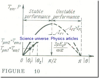
Since in a large power system the voltage V and the frequency f are constant, it follows that, given a constant excitation current, the power and the electromagnetic torque of a synchronous generator depend solely on the load angle │θ│. This sinusoidal relation is known as the power/angle or torque/ angle characteristic of a synchronous generator (Fig 10). For power and electromagnetic torque, it only differs in scale.
The power-vs-angle and torque-vs-angle characteristics give an insight into what happens in a synchronous generator as its load is varied.
The work done by the prime mover is converted to electric energy, and this is delivered to the line. As the torque developed by the prime mover increases, T > Tpm1 = Tem1 (point 1), the rotor is accelerated, and the load angle │θ│increases . After several oscillations about the synchronous angular velocity the balance between the driving torque supplied by the prime mover and the opposing electromagnetic torque developed by the generator is restored, T pmz = T emz (point 2) at a new value of the load angle │θ│: │θ2│> │θ1│.
A synchronous genera tor will give a stable performance if │θ│ varies from 0 to π/2 . At │θ│= π/2, the electric power is
A maximum Pmax = 3E0V/ (15.12)
and the electromagnetic is likewise a maximum
Tem,max = 3pE0V/ɷ (15.13)
The range of values π /2 – │θ│ defines the margin of stability for a synchronous generator. At │θ│ > π /2 a synchronous generator tends to be unstable. Now the driving torque supplied by the prime mover exceeds the opposing electromagnetic torque of the driven synchronous generator. The excessive torque (Tpm > Tem) accelerates the rotor still more, thereby leading to an increase in │θ│ and a further decrease in the torque of the generator, and so on, until the generator drops out of synchronism. The margin of stability π /2 – │θ│, of a synchronous generator at an increased load can be restored by increasing the excitation current (point 3).

