Speed Control of Induction Motors
In many cases three-phase induction motors are used in drives where speed control is not required. However, induction motors have valuable advantages to offer, namely reliability, low cost, simple design, high efficiency, and a relatively small weight. For this reason, it is only natural that efforts have been made to adapt them to service in variable-speed drives.
In the case of squirrel-cage motors speed control is effected through frequency control. In this approach the speed at which the magnetic field rotates is varied by adjusting the frequency of the current in the stator windings, or by varying the number of pole pairs of the rotating magnetic field so that the speed of the field is changed stepwise.
In the case of wound-rotor motors their speed is controlled by varying the resistance of the phase windings with the result that the slip of the rotor is caused to change continuously.
Speed control with varying frequency. Of all the existing methods of speed control the most promising one is by varying the frequency of the alternating current in the stator winding. The angular velocity of the rotating field is
ɷf = 2μf/p
Hence, a change in f causes the angular velocity of the field to vary in proportion. In practice, the voltage must also be changed. This is because, as follows from Eq. (14.10), the phase emf and, as a consequence, the supply voltage are proportiona1 to the frequency and flux. Since the flux must be maintained unchanged in any mode of operation, the voltage must be made to vary in proportion to the frequency (ignoring the voltage drops in the machine). Also this must be done so that the torque will not change as the speed is changed.
To evaluate the dependence of the torque on the current frequency in and the voltage across the stator, we will neglect the stator winding resistance rwl and the leakage inductive reactances of the stator, leak,l and of the rotor, leak,2 in Eq. (14.28) and use the expression for the slip frequency, Eq. (14.13):
T = 3PsV21/ɷr‘w2 = (3Pf2/2μf2r‘w2) V21 ≈ AV21/f2 (14.35)
where A is a constant.
Thus, if we wish to maintain the torque at a constant value as the current frequency is varied, we must vary the voltage across the stator winding. In other words, the condition for maintaining a constant torque as the frequency is varied takes the form
V1/f = const
If we vary both the current frequency and the voltage so that the above condition is satisfied, the speed-torque characteristic of the motor will remain flat, and the maximum torque will be almost independent of frequency (it will change markedly only at relatively low frequencies). At the same time, the output power will vary in proportion to frequency, because
P2 = Tɷrot
For example, halving the frequency would cause the output power to fall to half its original value as well.
Speed control by varying the number of pole pairs. This form of speed control is possible over a wide range of values, hut it involves a more sophisticated motor design and a higher cost.
So long as the supply frequency remains constant, the angular velocity of the rotating magnetic field is solely a function of the number of pole pairs that the stator-induced field has. Suppose that we have two independent windings on the same stator, one producing p pole pairs and the other, p‘ pole pairs. Then, when energized, the former will produce a field rotating at
n1 = 60f/p
and the latter will produce a field rotating at
n‘1 = 60f/p‘
Hence
n1/ n‘1 = p‘/p
The speed of the rotor will be different ill a similar way. The rotor winding must of course be of the squirrel-cage type.
The .number of pole pairs in one winding is in no way related to that in the other, and both may be chosen according to the conditions in which the motor is to operate. Speed control reduces to a stepwise change in the rotational velocity of the magnetic field. However, the speed of the rotor cannot be changed stepwise due to the inertia of the entire drive. For the rotor speed to change, it is necessary to make changes in winding connections.
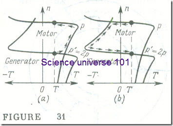
For a better insight into the process, let us construct two speed torque characteristics for an induction machine with a variable number of pole pairs, one for p pole pairs and the. other for p‘ = = 2p pole pairs, respectively (see Fig. 31 a and b). Suppose that as the speed of the rotating field is changed the same. As the speed is increased , that is, in going from p‘ to p pole pairs, the motor is first in a state close to the starting condition and the current undergoes a stepwise change. In going from p to p‘, however, that is, when the speed of the rotating field is decreased, the motor is first in the generating mode and delivers energy to the supply line. This mode is sometimes used to slow down an electric drive rapidly and economically.
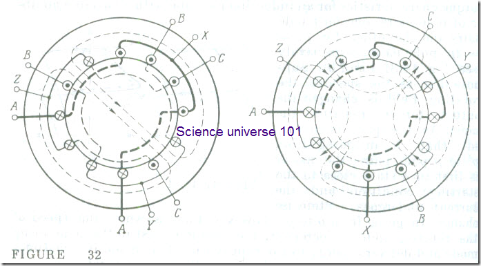
Two independent stator windings are provided only on small induction motors. In the case of large motors it is more advantageous to obtain a varying number of pole pairs by switching the coils of a single stator winding. The manner in which a single three-phase winding is switched from two to four poles is illustrated in Fig 32. For pole-pair ratios other than 1 : 2 a more complicated switching arrangement would be necessary, so it is used but seldom. In most induction motors the stator carries two independent windings for each of which the number of pole pairs can be switched in the ratio 1 : 2 or any other. In this way, such a motor can be set to operate at 3000, 1500, 1000, and 500 rpm.
Speed control with changes of rotor-circuit resistance. This form of speed control (often called rheostat speed control) is applicable to three-phase wound-rotor induction motors. It is effected by placing a three-phase rheostat in the phase circuits in much the same way as at starting (see Fig 24). In contrast to a starting rheostat, a speed-control rheostat must be designed to carry a sustained rather than a short-duration load current. The increase in the rotor-circuit resistance makes the torque-slip curve more drooping (see Fig 25). Given the same torque at the output shaft, an increase in the rotor circuit resistance by increasing the setting of the speed-control rheostat (rrhl < rrh2 < rrh3) will cause the operating point to move from one torque-slip curve to the next which corresponds to the increased rotor-circuit resistance (points 1 through 4 in Fig 25). Accordingly, the slip will increase too, and the speed of the motor will go down. In this way, the speed of the motor can be varied from the rated one to a full stop. Unfortunately this form of speed control involves relatively large power losses (see Sec. 14.11). If we neglect
the power lost in the stator core (see Fig 20), the power associated with the rotating magnetic field, Pr is the sum of the power lost in the rotor conductors (see the equivalent circuit in Fig 19)
PV2 = r‘w2 (I‘2)2
and the mechanical power
Pm = r‘w2 (1 – s) (I‘)2/s
The ratio
Pv2/Pm = s/(1 – s) = (nl – n)/n
indicates that the share of the mechanical power decreases in direct proportion to the decrease in the speed of the rotor, while the share of the power lost in the rotor-circuit resistance is increased. Hence, if we wish to reduce the speed of the motor by, say, 25 %, the rheostat brought into the rotor circuit must be such that a quarter of the energy associated with the rotating magnetic field is wasted as heat. Another limitation of this form of speed control is the fact that provision of a rheostat in the rotor circuit reduces the flatness of the speed-torque characteristic which implies that the speed of the motor becomes less stable. With the speed-control rheostat brought in, even minute changes in the load on the output shaft bring about substantial changes in the speed of the motor.


