Starting of an Indudion Motor
The starting performance of induction motors is an important consideration in their evaluation. This performance is basically determined by the following quantities: the starting current Istart . the starting torque Tstart . the starting time, and the economy of operation at starting. Makers’ data sheets usually quote the starting-to-rated ratio of a given quantity (Istart / Irtd or Tstart /Trtd) .
The behaviour of an induction motor at starting is determined by its construction, notably the rotor arrangement.
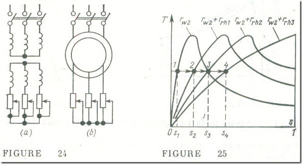
Starting of wound-rotor induction motors. The starting of a wound-rotor induction motor (see its equivalent. circuit in Fig 24 a, and its circuit diagram in Fig 24 b) can be improved substantially at the cost of some complication in its design and operation.
If we put s = 1 in Eq. (14.28). we will obtain an expression for the breakaway torque or the torque that a motor is required to develop in order to break away its load from rest to rotation
If it is required that a motor should develop its maximum torque at starting. Tstart =Tmax , then. in accord with Eq. (14.30) the resistance of a rotor phase winding should be
r’W2 = leak,1 X ‘leak,2 (14.34)
or
rW2 = leak,1 + leak,2
Since the resistance of a rotor phase winding is relatively small, the maximum breakaway torque can be obtained by placing in the rotor circuit a starting rheostat whose resistance per phase is
rrh ≈ ”leak,1 + leak,2
Then the torque-slip curve of an induction motor will have a peak at s = 1 (Fig. 25).
Just as the rotor begins rotating, the slip decreases, and so do the rotor emf and current with the result that the torque is reduced. For the motor to keep developing a torque close to the maximum one, the resistance of the starting rheostat must be gradually brought down. Finally, when the motor has come up to its rated speed, the starting rheostat must be shorted out.
Induction motors are sometimes fitted with a device to lift the brushes and to short-circuit the slip-rings in order to reduce mechanical losses and the wear of the rings and brushes.
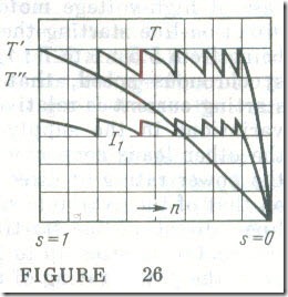
The inclusion of a rheostat in the rotor circuit affects the shape of the torque-slip curve. As follows from Eq. (14.32), this does not affect the maximum torque an increase in rrh only shifts the peak of the torque-slip curve towards the higher values of slip. For this reason all the torque-slip curves of an induction motor have their peaks at the same ordinate (see Fig. 25). As the starting rheostat is switched from step to step, the motor’s performance moves from one curve to another. It is usual to bring out the sections of the starting rheostat to contacts so that at starting the torque and current of an induction motor could be varied in steps as illustrated by the curves in Fig 26, the number of steps being the same as there are contacts in the starting rheostat. In the process, the starting torque varies from T" to T‘ .
The higher the starting torque must be, the closer it is to the maximum torque and the higher the starting current. For this reason it is only for extremely adverse starting conditions that the rheostat is chosen such that the starting torque is equal to the maximum one.
The power rating of the starting rheostat is chosen to be approximately equal to that of the motor so as to avoid overheating. For large-size motors the starting rheostats use oil cooling. In other cases use is sometimes made of the cheaper and simpler water cooled starting rheostats .
Of course, the use of a starting rheostat substantially improves the starting conditions for induction motors as it raises the starting torque and reduces the starting current. On the other hand, wound rotor induction motors are more expensive to build and less simple to maintain and operate, and have a low power factor and efficiency. For large-size induction motors this difference in efficiency and power factor is negligible, so the remaining limitations of wound rotor motors are the higher cost, the longer starting time, and the more complicated starting procedure.
The starting of a squirrel-cage induction motor. In most cases squirrel-cage induction motors are started "direct-on-line". Direct on-line starting is simple and takes up little time, but it calls for a simple switching device, such as a knife-blade switch or, in the case of high-voltage motors, an oil circuit breaker. In the case of direct-on-line starting the ratio of starting to rated current is high, being from 5.5 : 1 to 7 : 1 (for motors in sizes from 0.6 to 100 kW at synchronous speed, that is 750-3000 rpm). This short-duration starting current is relatively safe for the motor, but it brings about variations in the supply-line voltage which may adversely affect the other loads connected to the same supply line. For this reason the power rating of direct-on-line started induction motors depends on that of the available supply line. In the case of industrial supply lines, direct-on-line starting may be applied to squirrel-cage induction motors in sizes up to 1 MW or even bigger. In many cases, however, the power rating of motors may not exceed 100 kW.
There is one more drawback of direct-on-line starting to be kept in mind. For squirrel-cage motors the ratio of starting to rated torque ranges from 1 : 1 to 2 : 1 (see Fig 22). This implies that at a high starting current the motor develops a relatively small starting torque.
The starting of induction motors can be facilitated by reducing the starting current where necessary while keeping the starting torque as large as practicable. One way to minimize the starting current is to bring down temporarily the voltage between the stator phase terminals by connecting a three-phase inductor in series with the stator winding. In such a case, the starting torque is reduced in proportion to the square of the stator voltage , Eq. (14.33). For example, halving the starting torque would reduce the starting torque to one quarter of its full value. Unfortunately, this form of starting cannot be used to start a motor under load-it may so happen that the motor is not able to overcome the opposing mechanical moment at the output shaft.
As an alternative, the stator voltage can be brought down at starting by changing over from the delta connection normally used for the stator phases to the star connection temporarily. This form of starting is only applicable to squirrel-cage motors in sizes not over about 20 kW.
A much better starting performance is displayed by induction motors with a double squirrel-cage rotor. As its name implies, the rotor is made up of two squirrel-cage structures, the outer cage being used for starting, and the inner cage for normal running. The outer cage is usually made of manganese brass which has a higher resistivity than copper. The inner cage is made of copper, and its bars are usually larger in cross-sectional area. For this reason the outer cage has a higher resistance than the inner cage (by a factor of 4 or 5). As is the case with the simple cage rotor, the double cage is shorted at the ends by end-rings.
The bars are located in the outer and inner parts of the slots.
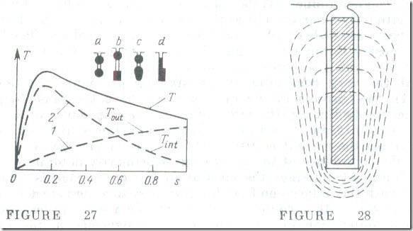
Owing to this arrangement there is a marked difference in leakage inductance between the outer and inner bars. The inner cage has a high leakage inductance because its bars are surrounded by a steel core with only a narrow slot at the top (Fig. 27 a and b). The outer cage has a lower leakage inductance because its leakage flux has its path mostly through the high-reluctance air gap between the rotor and stator and also across the slot width.
At the very beginning of the starting procedure (so long as s = 1), the currents in the rotor winding have the same frequency as the supply line; in the circumstances the impedance of the inner cage is mainly due to its high leakage inductance. Because of this. at starting the current is displaced from the inner cage. At the same time the impedance of the outer cage is primarily determined by its resistance. At starting, the current in the outer cage is almost in phase with the induced emf, and it gives rise to a high starting torque as is the case with a wound-rotor motor using a starting rheostat. The ratio of outer-cage to inner-cage currents depends on the ratio of their impedances; as a rule the current in the inner cage at starting is substantially lower than it is in the outer cage.
As the motor comes up to speed, the frequency of the currents in the rotor decreases, and so does the effect of the inductive reactance on the current distribution. At rated speed, the frequency of the rotor current is of the order of 1 Hz; in these conditions the leakage inductive reactance is very small and the current distribution between the two cages is determined by the ratio of their resistances. That is why the current in the outer cage is smaller than it is in the inner cage-its resistance and impedance are now small as they usually are in a single-cage induction motor.
The torque-slip characteristic of a double-cage induction motor may be looked upon as the sum of the characteristics of a motor in which the rotor winding has a relatively high resistance (see Fig 27, curve 1) and of a motor in which the rotor winding has a relatively small resistance (see Fig 27, curve 2).
Thus, the resistance of the rotor winding in a double-cage induction motor is a function of the slip-it is high at starting and low at the operating slip. This is the reason why a double-cage motor develops a higher starting torque at a lower starting current than a single-cage motor.
In some designs, the two cages are made by casting molten aluminium directly into the rotor slots (c and d in Fig 27). In such a case the aluminium also fills the neck between the top and bottom slots, and the top and bottom bars are joined together to form shaped bars.
A simplified modification of the double-cage type is the deep bar type. In a deep-bar rotor, the conductors are rectangular bars of a small width and a large height, placed in the deep slots of a rotor core. In the general case, alternating current is distributed nonuniformly over the cross-section of a conductor-this fact is utilized in a deep-bar cage motor. The distribution of the leakage flux in the case of a deep-bar cage is shown in Fig 28. The part of the bar lying deep in the slot links with a greater proportion of the flux than the part lying at the top of the same slot. At starting, the increased inductive reactance of the top part of the bar causes the rotor current to shift towards the outer portion of the bar. This is equivalent to an increase in the resistance of the rotor winding. This increase in rotor-winding resistance entails an increase in the breakaway torque of the motor, while the increase in inductive reactance due to the use of a deep bar serves to bring down the starting current. At the normal running speed the inductive reactance falls to a negligible value, the current is distributed over the cross-sectional area of each conductor almost uniformly, and the motor is running like an ordinary cage motor.
, From the view-point of design, a deep-bar cage motor is simpler than its double-cage counterpart. On the other hand, a double-cage motor may be built to develop a wide range of breakaway torque and various ratios of starting-to-rated current, so that it can be adapted to meet especially adverse starting conditions. Yet, deep-bar cage motors are used most frequently.


