The Equivalent Circuit for a Phase of an Induction Motor
In calculating the process taking place in an induction motor, resort is usually made to the equivalent circuit of one phase. This circuit is assumed to include fixed resistive and inductive elements and also a variable resistive element to represent the mechanical load applied to the motor shaft.
The difficulties. in developing such an equivalent circuit arise because, firstly, the frequency of the stator phase currents is f and that of the rotor phase currents is f 2 = f s , secondly, the stator phase has w1 turns and the rotor phase has w2 turns, thirdly, the two windings differ in the winding factors kw1 and kw2 and fourthly, the stator has ml = 3 phases and a squirrel-cage rotor has m2 = N phases. Therefore, all rotor phase quantities must be referred (or transferred) to the respective stator quantities.
To begin with, we will refer the rotor phase quantities to the stator phase frequency. To this end we consider an equivalent stationary rotor such that the rotating magnetic field of the motor remains unchanged and corresponding to the operating conditions. Since the rotating magnetic field remains unchanged, this implies that the energy transferred from the stator to the revolving rotor in operation is the same as that transferred to the equivalent stationary rotor.
Since the rotating magnetic field remains constant, the rms value of the emf in the phase winding of the equivalent rotor is given by the same equation as the rms value of the emf in the stator phase winding in operation, Eq. (14.11 b), so, subject to Eq. (14.14), it is
E2,st = 4.44fw2kw2Φr = E2/s (14.17)
where, for a squirrel-cage rotor, w2 = 1/2 and kw2 = 1.
The term E2st is the rotor phase emf referred to the stator frequency. It is one of the key quantities used in the design of induction motors, and its value is about twice that of the rms emf induced actually in a phase winding of the stalled rotor. This is because in the latter case the stator phase current is about 6.5 times the rated value, so that the voltage drop Zw1Il across it increases, and there is a decrease in the magnetizing current, Eq. (14.11a), which excites the rotating magnetic field, Eq. (14.11b).
For the rotating magnetic field to remain unchanged when the spinning rotor is replaced with a stationary one, it is necessary that. the currents in their phases, which have frequency f2 = f s in the former case and frequency f in the latter, be the same in amplitude and phase shift relative to the emfs that induce these currents. This is achieved by referring the phase current of the spinning rotor to the frequency f of the stationary rotor. In view of Eq. (14.17), the phase current of the spinning rotor in Fig 15 may be written as
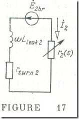
The right-hand side of the above equality corresponds to the equivalent circuit (Fig 17, in which Ė2br= Ė2,st) of a phase of the equivalent stationary rotor, where the current frequency is f , and the term rw2/s is represented by the sum of the rotor phase winding resistance rW2 and some additional resistance r2 (s) which is many times rW2 .
As follows from comparison of the equivalent phase circuits for the spinning and the stationary equivalent rotor, the current in them lags behind the emf by the same angle
Thus,
for design purposes an operating induction motor may be replaced with an equivalent stationary motor in which each rotor phase is shorted by a resistor
r2 (s) = rw2 (1 – s)/s
The power dissipated in this resistor, r2I22 , is equal to the mechanical power developed by the rotor in one phase.
Now we can refer the phase quantities of the equivalent rotor to the number of turns, the winding factor and the number of stator phases in much the same way as the secondary quantities of a transformer are referred to the primary turns (see Sec. 8.5).
The stator phase emf E1 is connected to the phase emf of an equivalent stationary rotor, E2,St , by a relation of the form
E1 = (w1kw1/w2kw2) E2.st = keE2.st
where Ire is the voltage transformation ratio of an induction motor.
As follows from the equivalent circuit (see Fig.17) for a phase of a stationary rotor
– Ė2.st = (rw2/s + jɷL1eak,2) İ2
= (rw2 + r2 + jɷLleak,2) İ2 = Zw2İ2+ r2İ2
Therefore,
– Ėl = (Z w2 + r2) keİ2
The rotor phase current, İ2 , may be replaced with the current referred to. the stator side, Eq. (14.16)
İ2 = (3w1kw1/m2kw2) İ’2 = kiİ’2
where k, is the current transformation ratio of an induction motor.
On substituting, we get
Ė1 = – (Zw2 + r2) kekiİ’2
The product keki = k is the transformation ratio of an induction motor .
Now we will introduce the rotor circuit impedance and resistance referred to the stator side into the equation of electric state for a stator phase of an induction motor
kekiZw2 = Z’w2 and kekir2 = r’2
In the stator phase circuit these elements would draw the same power and with the same phase angle between current and voltage as they do in the rotor phase circuit shown in Fig. 17.
Thus, the stator phase emf is
Ėl = – (Z’w2 + r‘2) İ’2
and the stator phase voltage, in accord with Eq. (14.11a), is
V̇1 = – Ėl + Zw1İ1 = Zw1İ1 + (Z’w2 + r‘2) İ’2 (14.18)
On the other hand, Ėl is proportional to the magnetizing current İl,oc . So, for the same reason as for a transformer .
– Ėl = Z12 İl,oc
where the term Z12 whose magnitude has the dimensions of ohms, represents in the equivalent circuit the magnetic circuit of the motor. Hence, the stator phase voltage may alternatively be defined as
V̇1 = Zwl İ1+ Z12 İl,oc (14.19)
Along with the stator current equation
İl = İl,oc + İ’2 (14.20)
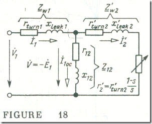
we may regard Eqs. (14.18) and FIGURE 14.18 (14.19) as corresponding to the Kirchhoff laws for the circuit in Fig. 18. Here, Z’w1 represents a stator phase, Z’w2 represents a rotor phase, Z12 represents the magnetic circuit of the machine, and r~ represents mechanical load.
In accord with Eq. (14.16), at synchronous speed the resistive element representing the mechanical load in the equivalent circuit is
r‘2 = r‘w2/s – r‘w2 = r‘w2 (1 – s )/ s = ∞
If we bring the motor to a complete slop, then s = 1 and r‘2 = 0 .
For this reason the test in which a motor is brought to a complete stop (the blocked-rotor test) may be called a short-circuit test since it is usually carried out at a very low stator voltage.


