The Equation of Electric State for a Rotor Phase of an Induction Motor
The revolving magnetic field induces in a rotor phase an emf, e2, at frequency f2 = P (nl – n)/60. We can express this frequency in terms of the supply-line frequency on dividing and multiplying the right-hand side of this expression by n1 . Then. in view of Eqs. (14.7) and (14.8). we get
f2 = fs (14.12)
which tells us that the slip frequency, f2 is equal to the product of the supply-line frequency by the slip.
The emf in a stator phase winding, e1. and the emf in a rotor phase winding. e2 are induced by a revolving magnetic field which is common to the two windings and is produced by the joint action of the stator current it and the rotor current i2 . However, e1 opposes a change in it. while e2 induces i2 Therefore, while the positive directions of et and it are the same (see Fig. 13), it is convenient to assume that the positive direction of i2 is opposite to that of e2 . This corresponds to the connection of the stator and rotor phase windings in opposition so that the resultant mmf of the motor is the difference between the stator mmf and the rotor mmf. This is also true of the primary and secondary emfs , currents and mmfs of a transformer (see Fig. 5 b).
The rotor phase current i2 sets up a magnetic field a part. of which avoids the stator winding. This part is responsible for the leakage flux linkage of a rotor phase winding, Ψleak,2 .
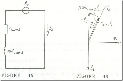
Thus. the equation of electric state in complex form for a rotor phase is
– Ė2= rturn.2İ2 + jsɷL1eak,2İ2 (14.13)
where rturn.2 is the resistance of the rotor turns, Lleak.2 = Ψleak,2 /i2is the leakage inductance of a rotor phase and sɷLleak.2 is the inductive reactance of a rotor phase.
By analogy with Eq. (14.11b), the rms value of the rotor phase emf is
E2 = 4.44fsw2kw2Φr (14.14)
where for a squirrel-cage rotor w2 = 1/2 and kw2 = 1 .
The equivalent circuit diagram of a rotor phase answering Eq. (14.13) appears in Fig.15, and the cone ponding phasor diagram is shown in Fig.16.
It is to be noted that Eq. (14.11a) and Eq. (14.13) are similar to Eq. (8.11a) describing the electric state of a transformer primary and Eq. (8.11b) describing the electric state of a transformer secondary in a short-circuit condition, that is, at V̇2 = 0 .
The Balance of MMFs in an Induction Motor
The revolving magnetic field set up by the stator of an induction machine remains stationary relative to that produced by its rotor. Therefore, with the rotor spinning, the mmfs produced by the stator and rotor currents may be treated as phasors which, when combined vectorially , give the mmf exciting the revolving magnetic field of the machine. In calculating these mmfs, it is important to remember that they are produced by currents in the coil sides that are distributed among several slots and are out of phase in space. This is accounted for by applying the winding factor which usually is less than unity.
Thus, by analogy with the mmf balance for a transformer, Eq. (8. t,), the mmf balance for an induction motor, with its rotor sta tionary or spinning, is
3w1kw1İ1 – m2w2kw2 İ2 = 3w1kw1İ1,oc (14.15)
Here we have accounted for the fact that the resultant mmf for a three-phase stator and rotor winding is 3/2 times that given by Eq, (14.4), and that the resultant mmf of an m2-phase winding is m2/2
times that of a single phase mmf.
On the basis of Eq. (14.15), the stator current may be expressed as
where
is the rotor current referred to the stator side. It is that part of the stator current which counteracts the demagnetizing effect of the rotor current.
When the motor is running (s ≼ srtd), the magnetizing current İ1,oc is practically equal to the stator current in the ideal no-load (open-circuit) condition. In order to determine the latter from a test, the rotor must be spinned by an auxiliary motor at the synchronous speed which is the speed of the rotating magnetic field (s = 0). In the circumstances, ‘the rotor current becomes equal to zero. Thus, with no load torque applied to the shaft, the open-circuit (no-load) current of an induction motor exceeds the ideal no-load (open-circuit) current due to the loss of power through friction in the rubbing parts, as heat in the winding rotor, etc.


