Induction Machines
Of the many types and forms of present-day electric machines those most commonly used are induction machines. ordinarily employed a motors.
An induction machine is all a.c. two-winding unit in which only one (usually the stator) winding is supplied with an alternating current at a constant frequency from an external source, while in the other (usually the rotor) winding currents arise from induction. The fact that the rotor currents are produced by induction is the basis for the name of this class of machines .
Induction machines are also called "asynchronous" because their operating speed is slightly different from the angular velocity of the revolving magnetic field set up by the stator winding .
An important advantage of induction machines is mat they have no readily damaged or wearing parts (such as a commutator) .
Large induction machines are made three-phase .small induction machines may be single- and two-phase . so they can operate off a two-wire supply line such units are widely used in household appliances .
A disadvantage common to induction machines is that speed and torque control is complicated and uneconomical.
Construction of a Three-Phase Induction Machine
As any induction machine, it consists of a stationary part, or the stator, and a rotating part, or the rotor.
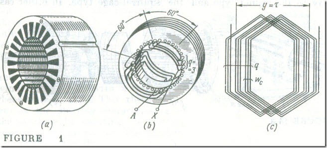
The stator. The stator of an induction machine is a hollow cylinder built up of electrical-sheet steel laminations insulated from one another by varnish (Fig. 1 a). Slots on its inner periphery carry three phase windings. Each phase winding consists of one or several coil groups connected in series and spaced equidistantly from one another. Figure 1 b shows the arrangement of one phase winding in stator slots. It consists of two coil groups, with A marking the start and X the finish of the phase winding.
The phase windings may be interconnected in a star or a delta and to a three-phase power supply. The currents flowing in the phase windings set up in the machine a revolving stator field which has p pole pairs, equal to the number of coil groups per phase winding.
This is achieved by disposing the phase winding in such a way that the coil groups in one are displaced around the stator circumference through an angle 120°/p with respect to the coil groups in the adjacent phase winding. As an example, for a four-pole machine ( p = 2) this angle is 60° (Fig 1 b) .
Each multiturn coil group of the stator winding is made up of q series-connected coils each having wc turns . The coils may be wound with the same or a different coil pitch, y . In the former case the sides of a coil are spaced 1800/p apart around the stator periphery, which corresponds to one pole pitch, y = τ . (Fig1 c). In the latter case, τ < y < τ the coils in a coil group are nested within one another (Fig 1 b).
The distribution of the phase windings among many slots not only improves the utilization of a cylindrical stator, but also optimizes the distribution of the magnetic field in the air gap between the stator and the rotor.
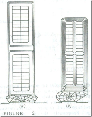
The stator core of an induction machine may have open slots (Fig 2 a) or semi-closed slots (Fig 2 b) . An advantage of semiclosed slots is that the machine has a lower reluctance and so it needs a smaller magnetizing current. On the other hand, it is simpler to place coils in open slots and the coils can be better insulated which is an important consideration for high-voltage machines.
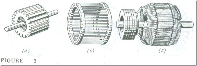
The rotor. Induction machines mainly differ in the rotor which may be the wound type and the squirrel-cage type. In either case the rotor is a cylindrical core (Fig. 3 a) assembled from electricalsheet steel laminations insulated from one another with varnish. The rotor core is mounted on a shaft which is supported in bearings. Slots on its outer periphery carry the turns of the rotor winding.
Most induction motors use a squirrel-cage rotor. It is less expensive to make and, what is very important, a squirrel-cage induction motor is Simpler to service and operate. The winding of a squirrelcage rotor consists of solid uninsulated copper or aluminium bars placed in rotor slots. These rotor bars are shorted together at the two ends of the rotor by end rings to form a structure resembling a squirrel cage which is why such induction motors are called "squirrel-cage". Frequently, the core laminations are stacked in a mould which is then filled with molten aluminium, so that the rotor bars, end rings and cooling-fan blades are cast at the same time in one economical process.
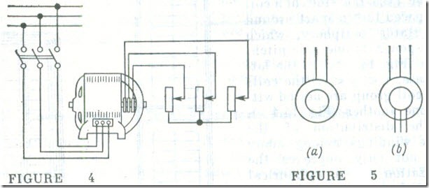
The winding of a wound rotor, also called a slip-ring rotor (Fig. 3 c) consists of coils of insulated wire, placed in slots in the rotor core. It is almost always three-phase and has the same number of coils as the stator. They are connected in a star on the rotor, and the three terminal leads are brought to three slip rings mounted on, but insulated from, the shaft. The slip rings .rotate in contact with brushes set up in fixed brush holders. The slip rings and the brushes connect the rotor winding in series with a three-phase rheostat (Fig. 4). This rheostat improves the starting characteristics of the machine by reducing the starting current and by raising the starting torque. Also the rheostat can be used for speed control.
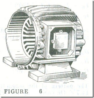
The graphic symbols used (in the Soviet Union) lo represent squirrel-cage (a) and wound-rotor (b) induction machines in diagrams are given in Fig. 5, and Fig. 6 shows the frame of an induction machine with its stator unwound.

