Three-Phase Transformers
All that has been said about a single-phase transformer may be carried over to each phase of a three-phase transformer operating into a balanced load. Let us take a closer look at how a three-phase transformer is arranged and operates.
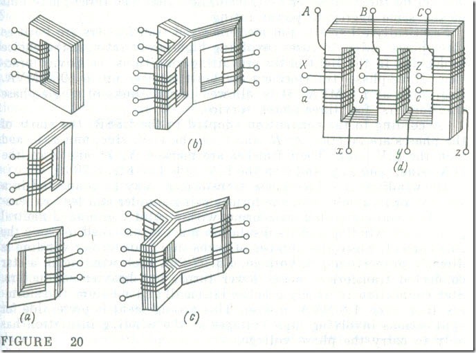
A three-phase system of currents or voltages might be handled by three single-phase transformers operating as a coordinated unit (Fig. 20 a). The actual practice, however, is to combine the three single-phase transformers into a single three-phase unit. In doing so, a good deal of materials is saved, and we will show how this is achieved.
To begin with, we build the core of a three-phase transformer by joining together the cores of the single-phase units and leaving unchanged their parts carrying the windings (see Fig. 20 b). This arrangement may be likened to a star connection of three electric circuits (see Fig. 4). As will be recalled, no neutral wire is needed for a three-phase system operating into a balanced load, because no current would flow in it. By doing well without a neutral wire, we save a fairly good quantity of copper. In our combined magnetic circuit, a neutral wire roughly corresponds to the common middle Iimb (or leg) (see Fig. 20 b). In a balanced three-phase system, no common limb is needed and may be dispensed with (Fig. 20 c), because the sum of the instantaneous values of the three magnetic fluxes is zero at any instant.
The symmetrical core of Fig. 20 c is poorly adapted to fabrication and is usually replaced with an unsymmetrical one (see Fig. 20 d) which may be looked upon as a straightened version of a symmetrical core. In this unsymmetrical core the balanced (symmetrical) system of primary currents induces a symmetrical (balanced) system of magnetic fluxes (see Sec. 7.1). Since, however, the reluctances of the core limbs are all different" the magnetizing currents in the phases are different too. Fortunately, this difference in magnetizing currents between the phases is immaterial.
An assemblage of three single-phase transformers is more expensive than one three-phase transformer of the same power rating; it takes up a larger floor area, and its efficiency is somewhat lower. On the other hand, only one single-phase transformer needs to be kept in reserve for use in an emergency or during repairs, because it is highly improbable that a fault will occur in the three units at the same time, whereas scheduled maintenance can be carried out on each in turn. With a three-phase transformer, a similar three-phase unit has to be kept in reserve. Thus, with all other conditions being equal, an assemblage of three single-phase transformers is more reliable in service. Last but not least, it is simpler and less expensive to move and set up three single-phase transformers than one three-phase unit of the same aggregate power rating.
Practically all small- and medium-sized transformers are built as three-phase units. In cases involving high-power ratings, the choice is decided in the light of the prevailing conditions. In Soviet practice, three-phase transformers are built in sizes up to 1000 MVA. Beginning at 1.8 MVA, it is allowed to use hanks of single-phase transformers for three-phase service.
According to the convention adopted in the USSR, the starts of the phases are labelled A, E, and C on the H.V. side, and a, b, and c on the L.V. side. Their finishes are marked X, Y, and Z on the H.V. side, and x, y, and z on the L.V. side (see Fig. 20 d).
The windings of a three-phase transformer may be connected in a star (Y) or in a delta (Δ), the former being simpler and less expensive. In a star-connected transformer with a solidly grounded neutral point, each winding and its insulation must he designed to carry the line current. Since the number of turns in a transformer winding is directly proportional to voltage, Eq. (7.2h), each winding in a star connected transformer needs fewer turns, hut heavier conductors. Star connection is widely practised in small and medium transformers (not over 1.8 MVA in size). This arrangement is preferable for applications involving high voltages as the winding insulation has only to carry the phase voltage.
The delta connection of the transformer windings is warranted in cases involving heavy currents. A star-delta (Y-Δ) connection is preferable in high-power transformers if no neutral wire is needed on the L.V. side.
As follows from the relations applicable to a three-phase system (see Sees. 3.2 and 3.3), in three-phase transformers only the phase voltage ratio V1Ph/V2Ph is approximately equal to the turns ratio, wl/w2 , and the line voltage ratio depends on how the windings are interconnected. In a star-to-star or a delta-to-delta connection, the line voltage ratio is equal to the phase transformation ratio. In a star-to-delta or a delta-to-star connection the line voltage ratio is smaller or greater than the transformation ratio by a factor of √3 . Hence, by changing the interconnection of its windings, we can always vary the secondary line voltage of a transformer.

