Instrument Transformers
These may be current transformers and voltage transformers.
They are used, firstly, for the purpose of changing currents or voltages in a power circuit to values which render them convenient for measurement, and secondly in order to extend the range of the associated instruments.
Voltage instrument transformers are used in conjunction with voltmeters, frequency meters, the potential (shunt) circuits of wattmeters , electricity meters and phase meters, and relays. Current instrument transformers are used in conjunction with ammeters and the current (series) circuits of some instruments, and relays.
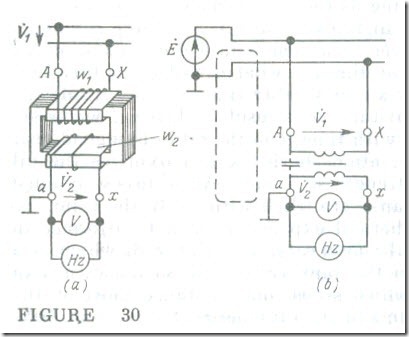
A schematic diagram of a voltage (or potential) transformer is shown in Fig. 30 a, and its symbolic representation in Fig 30 b. This type of transformer is similar to a small-power transformer. Its primary, or H. V., winding with w1 turns is connected in the circuit whose voltage V1 is to be measured, and its secondary, or L.V., winding at a voltage V2 and with substantially fewer turns w2 is connected in parallel to a voltmeter and the potential circuits of other instruments. As a rule, both windings are of the concentric type, with the H.V. winding enclosing the L.V. winding as in a power transformer (in Fig. 30 a they are shown separately). One terminal of the secondary winding and the transformer frame are grounded. This is done as a precaution in case of a damage to insulation and also to return to earth the current path shown by the dashed line in Fig. 30, via the capacitance between the primary and secondary windings. Unless returned to ground, this current might impair the accuracy of measurement.
The voltmeter and the potential circuits of the other instruments connected to a voltage transformer have a relatively high resistance (of the order of several thousand ohms), which implies that a voltage transformer operates under conditions very close to the open-circuit condition of a power transformer. Therefore the voltage drop across the primary winding, z1I1, and across the secondary winding, z2I2 of a voltage transformer is very small, so we may deem that
V1 ≈ E1,oc and V2 ≈ E2,oc Also, since by analogy with Eq. (8.13)
E1,oc / E2,oc = w1/w2 = n12
where n12 is the transformation (turns) ratio, then
V1 = n12V2 (8.28)
As is seen, the secondary voltage is related to the primary voltage by a constant ratio. In consequence, by measuring the low voltage V2 we immediately obtain the high voltage V1 .
When the chosen positive directions of voltages (see Fig. 30) are the same relative to the like transformer terminals, the secondary and primary voltages must be in phase. Therefore, the windings of a voltage transformer are always connected to give phase displacement group 0 (see Sec. 8.11), and the winding terminals are labelled A-X and a-x. The same phase voltages in a voltage transformer and in the associated measuring instrument(s) are made equal by suitably connecting the secondary terminals of the transformer to the instrument terminals. Of course, a correct phase relation is important for a wattmeter and an electricity meter and not for a voltmeter or a frequency meter. Most voltage transformers are wound for a standard secondary voltage of 100 V.
The ratio of the primary to the secondary voltage would always be the same if the voltage drops across the transformer windings were zero. Actually these drops are anything but zero, and are a source of two errors, the voltage ratio error and the phase angle error.
The voltage ratio error is usually expressed as a percentage and is defined as the ratio of the error in the measured primary voltage to the true value of that voltage
where Vl.meas is the measured primary voltage, and Vl is the true value of primary voltage.
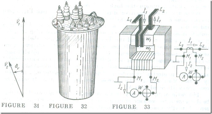
The phase angle error is defined as the angle, δv, between the primary voltage phasor and the secondary voltage phasor (Fig.31 on a phasor diagram drawn up similarly to that in Fig.13 . The phase angle error is expressed in minutes of arc, and is taken as positive if the secondary voltage phasor leads the primary voltage phasor.
For voltages up to 6 kV, potential transformers come as air-natural-cooled dry units. For voltages in excess of 6 kV they are oil immersed units. Often, potential transformers are made three-phase. A general view of a three-phase potential transformer is shown in Fig. 32.
A current transformer is connected on its primary side as an ammeter, that is, in series with the line whose current is to be measured or controlled (Fig. 33), while its secondary winding is connected directly to an ammeter or the current (series) coil of a wattmeter (or similar instruments). The total resistance of an ammeter or of the current coil of a meter is very small (being less than 2 Ω), so a current transformer operates under conditions approaching the short circuit condition of a conventional transformer. The secondary voltage of a current transformer depends on the voltage drop across
the relatively small resistance of the instrument load and connecting wires (being usually 1-12 V). The low secondary voltage corresponds to a small secondary emf, E2, and, in consequence, to a small value of magnetic flux in the core of the current transformer
E2 = 4.44fw2Φm (8.29)
It takes an insignificant mmf, I1,ocw1, to excite such a flux, so in the equation
İ1w1 = İ2w2+ İ1,oc wt (8.30)
this quantity may be neglected, and we may write
İ1w1 = İ2w2
or
I1 = (w2/ w1) I2 = n21 I2 (8.31)
Thus, the primary current call be determined by multiplying the secondary current by a constant transformation (or turns) ratio n21 In this way we can measure the current in an H.V. power line by determining a small current without running any safety hazard.
Current transformers are often used to measure heavy currents in plants or lines operating at below 1 kV. With a proper connection of the current-transformer leads to the meter terminals, the current in the instrument load will be in phase with that in the current-transformer primary. When an ammeter is intended for permanent use with one and the same current transformer, its scale can be directly laid out in values of the primary current. The rated secondary current is the same for all current transformers, the standard value being 5 A (or 1 A in some special cases).
The current ratio in current transformers is not always the same owing to the effect of the mmf İ1,ocw1 which has been so far neglected.
This effect is the source of two errors, the current ratio error, fi , and the phase angle error, δi . They are defined in about the same manner as for potential transformers, except that current is inserted in the applicable equations instead of voltage.
In most cases the primary current of a current transformer is many times the secondary current. For this reason the number of primary turns, WI’ is small, being a fraction of the number of secondary turns w2 . When large currents are .to be measured, the primary is most often a single turn which is formed by running the line through the window of the core. Since wl < w2 . the primary voltage is a few hundredths of a volt for a secondary voltage of several volts .
The value of İ1 depends on the circuit in which it is measured.
Any increase in the resistance of the current-transformer secondary . cannot practically affect the value of İ1 but, as follows from Eq. (8.30), this can raise the mmf İ1,ocwl due to a reduction in İ2 , Because of this, as the resistance of the secondary circuit is increased, the actual condition deviates progressively more from that essential to the accuracy of a current transformer: İ1,ocwl << I2w2 . This is why it is usual to state the maximum resistance of the instrument load that can he put on the secondary without exceeding the limits of ratio and phase angle errors.
when current is passing through the primary, the secondary of a current transformer must always be shorted either through the current coils of meters or through the shorting switch provided as part of the transformer. The reason for this precaution is as follows. When the secondary circuit of a current transformer is open, the secondary current I2 is zero, while the primary current Il remains practically unaffected. Now all of the primary current is acting as a magnetizing (or exciting) current, that is, by virtue of Eq. (8.30), I1,ocwl = I1w1 , whereas under normal conditions I1,ocwl accounts for as little as 0.5% of I1w1, This manifold increase in mmf leads to a very large build-up of the magnetic flux (solely limited by the saturation of the core). Since, by Eq. (8.29), the secondary emf E2 is proportional to the magnetic flux, it may run as high as several hundred volts, while in current transformers for large currents it may be as high as 1.5 kV. This is obviously a source of hazard to human life. Also, the core losses go up [see Eqs. (7.11) and (7.12)], more heat is generated, and the core expands. Either is highly detrimental to the insulation and might finally lead to its break-down and a fault to ground on the H. V. side.
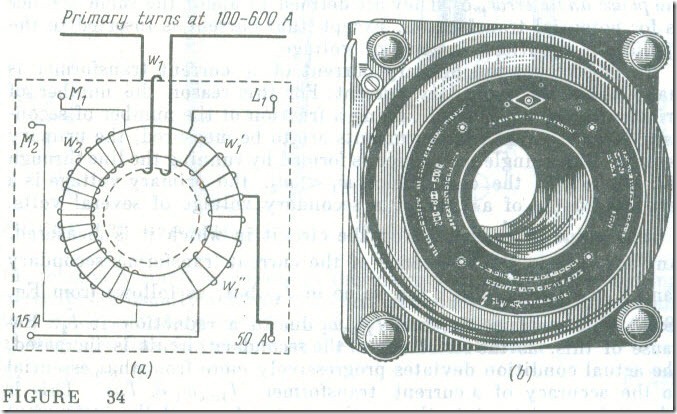
The mmf required to excite a magnetic flux in a core decreases as the core reluctance is brought down. For this reason the cores for precision current transformers are made continuously wound (to avoid joints) from materials such as Permalloy. An example is the multi-range portable current transformer shown in Fig. 34 a.
It has one secondary winding w2 and three primaries: w1 for measuring currents up to 600 A, w’1 for currents up to 50 A, and w’1 + w”1 for up to 15 A. How this current transformer looks like is shown in Fig. 34 b.
In addition to accuracy, current transformers are often required to have a high stability towards short-circuits because their primaries are connected in power lines where short-circuits are likely to develop, and also because current transformers themselves are connected to relays used to disconnect a power line or an electric installation in the case of a short-circuit. I n other words, a current transformer must be capable of withstanding (momentarily) the short circuit current and operate the relay(s) that will de-energize the faulty equipment.
One way to enhance the accuracy of a current transformer is to keep the effect of its exciting mmf, İ1,ocwl , to a minimum. This can be done, among other things, by making its rated primary mmf, I1,rtdwl . as large as practicable. For precision current transformers it should be no less than 500 A. If the rated primary current is less than 500 A, the primary must have several turns. As an example, tor a rated primary current of 100 A the primary should have at least five turns. If high accuracy is not a factor (such as when a currant transformer is connected to an ammeter or an over current relay), the rated primary mmf may be substantially smaller.
Currents of 500 A and more are measured with single-turn through type current transformers which include the split-core type shown
in Fig. 35. A split-core current transformer (Many authors class this type of current transformer as a split-electromagnetic ammeter. – Translator’s note) . is used to measure approximately currents from 20 to 1000 A at low voltage. Its core is made up of two U-shaped parts pulled together by a strong spring and fabricated from electrical-sheet steel punchings stacked up and polished at the mating faces. When using a split-core current transformer, the operator moves the handles together, opens the tongs, puts the instrument around the line conductor, and releases the handles-the spring will then force the tongs to close. Now the line conductor passing through the tongs acts as the primary. The secondary is wound on the core and is connected to an ammeter.
Instrument (both potential and current) transformers are grouped into accuracy classes on the basis of their limits of ratio error. For potential transformer in accuracy class 0.5, the limit of ratio error is +0.5% and the limit of phase angle error is ±20′, with the primary voltage being from 80% to 120% of the rated value. For a current transformer in accuracy class 1 the limit of ratio error is +1.0%and the limit of phase angle error is ±90′, with the load impedance being from 25% to 100% of the rated value and with the primary current being from 120% to 10% of the rated value.
Connections between an instrument transformer and its load should be made according to the markings on their terminals which on potential transformers are labelled in the same way as on power transformers (A–X, a–x, etc.). In the case of current transformers the start and finish of the primary are labelled (at least in the Soviet Union) Ll and L2 (where the letter L stands for "line"), while the start and finish of the secondary are marked M1 . and M2 (where the letter M stands for "meter").
The manner in which instruments are connected via potential and current transformers into a single-phase circuit is illustrated in Fig. 36. For measurements in three-phase. three-wire lines several instrument transformers are required in the general case. For example. in order to measure active power (see Fig. 13 a) one will need two current transformers and two potential 4 transformers (or one three-phase potential transformer).
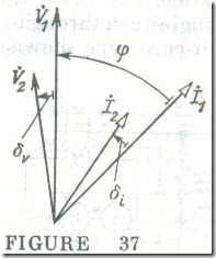
Readings of a wattmeter (or a watthour-meter) connected via potential and current transformers must be multiplied by the product of the transformation ratios of the two trans-formers. The errors associated with instrument transformers affect the accuracy of wattmeters . The phase angle error has an especially strong effect mainly at large phase angles between the primary voltage and current. Because of this, wattmeter readings are proportional not to the power factor cos φ , but to cos (φ + δv – δi ) (Fig. 37). The phase angle errors may combine because it often happens that δv < 0 and δi > 0 .


