External Characteristics of a Transformer
Consider the performance of a transformer for several values of the complex load impedance Z2 = z2 ∠ φ2 If the primary voltage is constant and equal to its rated value, V1 = V1.rtd,variations in the complex load impedance will bring about changes in the primary and secondary currents İ1 and İ2 and in the secondary voltage V̇2 of the transformer.
The difference between the no-load and full-load secondary voltages expressed in terms of the former, with the primary voltage held constant, is called the voltage regulation of a transformer. To find it, it is usual to refer (transfer) the secondary voltage to the primary side. Then, V’2 = (w1/ w2) V2 . The no-load secondary voltage is practically equal to V1,rtd Therefore, we may write V1,rtd – V‘2 . Ordinarily, the voltage regulation of a transformer is expressed as a percentage of the rated primary voltage
From the simplified equivalent circuit diagram of a transformer (see Fig. 17 a) and from its phasor diagram (see Fig. 17 b) it follows that
V1,rtd – V’2 ≈ (rsc cos φ2 + sc sin φ2 ) I1
or, by Eq. (8.20),
ΔV% = ( I1 / V1,rtd) (rsc cos φ2 + sc sin φ2 ) X 100% (8.21).
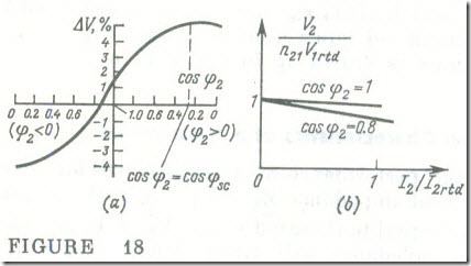
A plot of voltage regulation as a function of the load power factor, cos φ2 , for I1 = const, is drawn up in Fig.18 a . The voltage regulation is a maximum when cos φ2 = cos φsc , in which case the internal voltage drop phasor ZscI1 is in the same direction as the primary voltage phasor VI (see Fig.17 b). In consequence,
V‘2 = V1 – ZscIl
By plotting variations in the secondary voltage V2 as a function of the load current I2 for a constant load power factor and the rated primary voltage, we obtain what is known as the external characteristic of a transformer. As often as not, the external characteristic
 of a transformer is constructed on a per-unit basis, that is, in terms of the ratio of the secondary voltage to its rated value, V2.rtd = n21V1,rtd in the open-circuit condition, and its load current ratio
kload = I2/I2.rtd (8.22)
where I2.rtd = I1.rtd /n21 is the load current at the rated primary current I1 = I1.rtd In view of Eqs. (8.20) and (8.21), the external characteristic of a transformer on a per-unit basis is defined by the following equation
V2/n21Vl. rtd = (1- ΔV %/100) = 1-kload (I1. rtd/V1. rtd)
X (rsc cos φ2 + sc sin φ2)
For φ2 > 0, the external characteristic is shown in Fig. 18 b.
