The Short-Circuit Condition of a Transformer
This condition may arise as a result of a fault fraught with grave consequences (overheating and break-down), or it may be produced for testing purposes in which case it is called the short-circuit (or load loss and impedance) test.
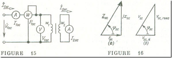
The short-circuit test is carried out by short-circuiting the secondary winding and applying a low voltage to the primary winding sufficient to cause the rated full-load current, I1,sc = I1.rtd , to flow. The objective of the test (Fig. 15) is to measure the power dissipated in the conductors, the impedance voltage, etc. It is one of the mandatory tests applied at the maker’s works to a finished transformer .
In the short-circuit test when V2 = 0, the emf E2,sc induced in the secondary winding is, as follows from Kirchhoff’s voltage law, Eq. (8.11b), equal to the sum of the voltages across the resistance
and inductive leakage reactance of the secondary winding
Ė 2,sc = – (r2 + jleak.2) İ2,sc
while under the operating conditions
Ė 2 = – (V̇2 + r2 İ2 + jleak,2İ2)
The primary voltage applied in the short-circuit test, Vl,sc, in order to cause a full-load rated current, Il,sc = Il,rtd, to flow amounts approximately to 5-10 % of the rated primary voltage, Vl,rtd . Therefore the rms secondary emf, E2.sc , is a mere 2 % to 5 % of the rms emf, E2, under normal operating conditions. The magnetic flux in the core, Eq. (8.1h), decreases in proportion to the emf , and so do the magnetizing current and the core losses which are proportional to Φ2. In consequence, it is legitimate to think that during a short-circuit test all of the primary power in the transformer, Pl,sc, is equal to the copper (conductor) losses in the primary and secondary windings
P1,sc= r1I21,sc+r2I22,sc= r1I21,sc+ r’2I’22, sc
The magnetizing current I1,oc is negligibly small, therefore, by Eq. (8.10a), Il,sc = I‘2,sc , and
P1,sc= (r1+r’2)I21,sc= rscI21, sc (8.14)
As the apparent power rating, Srtd, of a transformer is increased, the short-circuit active power, P1,sc, goes down in relative terms. For Srtd = 20-5 KV A, the ratio P1.sc/Srtd is 3-3.7%, while for Srtd = 320-5600 kV A, the figure is 2-1 %.
Using the value of load loss found in a short-circuit test, P1,se, and the full-load rated current Il,sc = I1,rtd, we can, on the basis of Eq. (8.14), determine the short-circuit resistance of the transformer
rsc = P1,sc/I21,sc (8.15)
To keep the size of a transformer to a reasonable minimum, the designer has to choose the current density in the conductors and the magnetic flux density (magnetic induction) in the core such that the temperature rise of the transformer will remain within the safe limits. For this reason, in finding the load loss, the value of rsc found by a short-circuit test must he re-scaled to a temperature of 75°C (see Table 1.2).
The short-circuit inductive reactance of a transformer may be deemed independent of temperature. Therefore, it is found directly from the results of a short-circuit test
Hence the short-circuit impedance of a transformer, as re-scaled to an operating temperature of 75°C, is
Figures 16 a and b show an impedance triangle and a geometrically similar short-circuit triangle in which the sides represent the active and reactive components of the short-circuit primary voltage, V1,sc, as a percentage of the primary rated voltage, V1,rtd . The two components are found at I1,sc = I1.rtd so
νsc, a = (rscI1, rtd/V1, rtd) X 100%
νsc, r = (scI1, rtd/V1, rtd) X 100%
and the hypotenuse of the short-circuit triangle is
νsc = (ZSCI1, rtd/V1, rtd) X 100%
where νsc is called the impedance voltage of a transformer. It is a very important parameter on the basis of which we can determine variations in the secondary voltage of a loaded transformer (see Sec. 8.8). It is usual to state the impedance voltage of a transformer on its nameplate.
The value of νsc increases with increasing rated voltages across the transformer windings. The reason is that at an increase in the thickness of conductor insulation, the leakage flux linkages go up, and so do the two leakage reactances , leak,1 and leak,2 In a transformer rated at anywhere between 5000 and 5600 kVA and with a rated voltage of 6.3 and 10 kV on the H.V. side, the impedance voltage is 5.5%. In a transformer rated at anywhere between 3200 and 4200 kVA and with a rated voltage of 35 kVon the H.V. side, the impedance voltage is 7%.
The short-circuit test can also provide a check on the turns (or transformation) ratio. In the short-circuit condition the term I1,oc w1 in Eq. (8.4) is negligible in comparison with the other two terms, so
w1I1,sc ≈ w2I2,sc (8.18)
Hence the transformation (turns) ratio is
n2I = w2/w1 ≈ I1,sc/ I2,sc (8.19)
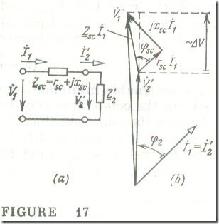
If we neglect the open-circuit (magnetizing) current I1,oc of a transformer and find its rsc and sc by a short-circuit test, we can draw up a simplified equivalent diagram (Fig. 17 a) for which a phasor diagram is drawn up in Fig. 17 b.


