Parallel Operation of Shunt Generators
In practice cases often occur where it is advantageous to feed loads from two or more generators operating in parallel. Let us see how this is done, taking the simplest example. that of shunt generators.
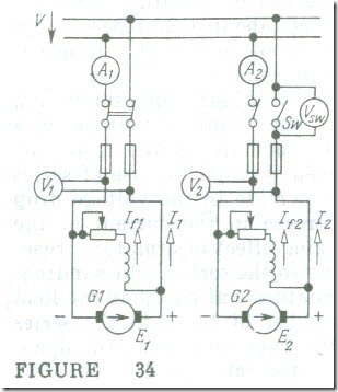
Suppose we are to bring a second generator (Fig. 34) into a line where a first generator, G1 maintains a voltage V. The procedure is as follows. First the armature of the incoming generator is brought up to the speed of the first generator with the aid of a prime mover (a turbine, a Diesel engine. etc.). Now the field current, If2 of the second generator, G2, is adjusted so that its emf, E2, is equal to the line voltage. Then a check is made to see that the generator has the same polarity as the line by reference to a voltmeter Vsw: if the voltmeter reads zero, the single-pole switch Sw may be closed, thus bringing the second generator in.
Since the generator emf is balanced by the line voltage, its current after switch-on is
I2= (E2 – V)/rarm,2 = 0
The load on the second generator is raised by increasing its field current. This leads to an increase in the emf E, of the second generator, with the result-that this, firstly, raises the load current of the second generator to 12 and, secondly, raises the line voltage V. The emf of the first generator which carried all the load remains unchanged, so the increase in the line voltage leads to a reduction in the load on the first generator.
On interacting with the magnetic field set up by the poles, the armature current I2 of the second generator produces a braking torque which causes the generator to slow down. In response, the speed governor of the second generator increases the amount of working fluid (steam, water, oil, etc.) fed to the prime mover, and the second generator is restored to its specified speed . In this way, the second generator and its prime mover have taken over their share of the total load on the line. The situation is reversed for the first generator, G1, in which the reduction in I1 unloads its prime mover.
If it is required to shift all of the load onto the second generator, it will suffice to reduce the excitation of the first gradually and to increase the excitation of the second, while maintaining the line voltage V at a constant value. When the emf of the first generator becomes equal to the line voltage, its current will drop to’ zero (which is another way of saying that it is carrying no load any longer), and it may be disconnected from the line. The speed governors of the prime movers will assist in load shifting.
If we leave the first generator connected to the line and keep reducing its field current, its armature current will be reversed
I1 = (V – E1)/rarm,1
Now, a driving rather than braking torque will be developed, and the machine will begin running as a motor. Since this might cause a heavy damage to the prime mover, all generators operating in parallel are fitted with a reverse current relay which automatically disconnects the associated generator just as its current undergoes a reversal.
Thus, by varying the excitation of paralleled generators, we can divide the load between them in any ratio.
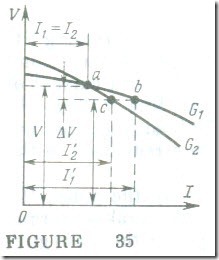
Let us see how the load is divided between two generators whose external (load) characteristics differ in slope (Fig. 35). Suppose that initially their excitation was adjusted in such a way that the two generators were loaded identically, and their load curves intersected at the balancing point a for a given line voltage V. If, now, we increase the load current, the current in each generator will also go up, and so will the voltage drop across the armature winding resistance and armature reaction. In consequence, the line voltage will go down by ΔV. However, as can be seen from the load characteristics, this reduced voltage
V’ = V – ΔV
corresponds to different values of current, I’1 and I’2 This means that the load is no longer shared equally between the two generators: the generator having the flatter load characteristic takes a greater share of the load, I’1 . This inequality is easy to correct (by , say, increasing the excitation of the second generator), however this complicates the duty of attending personnel. In fact, the correction is difficult to accomplish if the variations are rapid. For this reason it is required that the generators to be used for parallel operation should have identical external characteristic or that suitable automatic control should be provided.


