frequency stability
The frequency stability of an oscillator is the amount by which its frequency drifts from the desired value. It is desirable that any frequency drift should be very small and the maximum allowable change in frequency is normally specified as so many parts per million, e.g. ± 1 part in 106 would mean a maximum frequency drift of ± 1 Hz if the frequency of oscillation were 1 MHz but ± 100 Hz if the frequency were 100 MHz. The frequency stability of an oscillator may be short-term (minute-by-minute) or long-term (hours, days or even longer).
The frequency of an LC oscillator has hitherto been taken as being equal to the resonant frequency of the tuned circuit, and the frequency of an RC oscillator as a function of the selected RC values. However, the oscillation frequency also depends on the load impedance into which the oscillator works and the parameters of the transistor or op-amp employed.
Load on the Oscillator
The frequency of oscillation is not independent of the load into which the oscillatory power is delivered. If the magnitude of the load
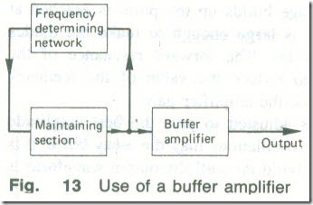
impedance should vary, the oscillation frequency will not be stable. Variations in the external load can effectively be removed by inserting a buffer amplifier in between the output of the oscillator and the load (see Fig. 13). The buffer amplifier serves the dual purpose of isolating the oscillator from any changes in the load and increasing the output voltage level. The amplifier is an ordinary audio- or radio-frequency amplifier, depending on the oscillator frequency.
Variations in Supply Voltage
The parameters of a transistor, or of an op-amp, such as current or voltage gain, and input and output capacitances, are functions of the current taken from the power supply and hence of the supply voltage. Any change in the power supply voltage will cause one or more of these parameters to vary and will cause the oscillation frequency to drift. This cause of frequency instability is fairly small but, if necessary, the stabilization of the power supply voltage can always be improved.
Circuit Components
Any changes in the temperature of the circuit components will produce changes in the inductance and capacitance values and thereby alter the oscillation frequency. Temperature changes alter the inductance by changing both the dimensions of the wire and the former on which the inductor is wound. The inductance will increase with increase in frequency. Capacitance is a function of temperature because the capacitor plates expand or contract slightly, and also because the permittivity of a dielectric is not independent of temperature. The capacitance will decrease with increase in frequency. The frequency stability can be improved by minimizing temperature changes by (a) keeping the power dissipated within the active device small, (b) keeping the frequency-determining components well clear of any heat sources, and (c) (if the expense is justified) mounting the components inside a thermostatically controlled enclosure or oven. Temperature changes can also be minimized by keeping the oscillator permanently switched on. When all temperature changes have been minimized a further improvement in frequency stability can be achieved by using components having small and/or opposite temperature coefficients. The practical difficulty inherent in the use of negative and positive temperature coefficient components is that they must track one another over a range of temperatures and they must be reproducible in quantity production .
If the temperature increases the inductance will increase by an amount xL and the capacitance will decrease by an amount yC. The frequency of oscillation will then change from fosc = 1/2μ√(LC) to
F’osc = 1/{ 2μ√[LC(1 +x)(1-y)] } (7.10)
Fosc / F’osc = 1/√(1 +x-y) ≏ 1-(x-y)/2 (7.11)
therefore
F’osc = Fosc[1- x-y)/2]
Example 6
The inductance of a 10 MHz tuned collector oscillator increases by 50 parts in 106, and the capacitance falls by 60 parts in 106, for every 1 °C rise in temperature. Calculate the change in temperature that will produce a 300 Hz increase in the frequency of oscillation.
Solution
x = 50 X 10-6 per °C and y = 60 X 10-6 per °C
l0x 106+300 = (l0x 106)[1-(50x 10-6-60x 10-6)/2]t °C
300 = (- 10(50 – 60)/2]t °C
300 = 50t °C, or t = 6°C (Ans.)
Crystals oscillators
The best frequency stability that can be achieved with an LC oscillator is limited by economic considerations to about ± 10 parts in 106 per °C, and if better stability is required a crystal oscillator must be used. A crystal oscillator is an oscillator circuit in which the frequency-determining network is provided by a piezo-electric crystal.
Piezo-electric Crystals
A piezo-electric crystal is a material, such as quartz, having the property that, if subjected to a mechanical stress, a potential difference is developed across it, and if the stress is reversed a p.d. of opposite polarity is developed. Conversely, the application of a potential difference to a piezo-electric crystal causes the crystal to be stressed in a direction depending on the polarity of the applied voltage.
In its natural state quartz crystal is of hexagonal cross-section with pointed ends. If a small; thin plate is cut from a crystal the plate will have a particular natural-frequency, and if an alternating voltage at its natural frequency is applied across it, the plate will vibrate vigorously. The natural frequency of a crystal plate depends on its dimensions, the mode of vibration, and its original position or cut in the crystal. The important characteristics of a particular cut are its natural frequency and its temperature coefficient; one cut, the GT cut, has a negligible temperature coefficient over a temperature range from 0 °C to 100 °C; another cut, the AT cut, has a temperature coefficient that varies from about + 10 p.p.m./°C at 0 °C to 0 p.p.m./°C at 40°C and about +20 p.p.m/°C at 90°C.
Crystal plates are available with fundamental natural frequencies from about 4 kHz up to about 10 MHz or so. For higher frequencies the required plate thickness is very small and the plate is fragile; however, a crystal can be operated at a multiple of its fundamental frequency and such overtone operation raises the possible upper frequency to about 100 MHz.
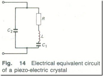
The electrical equivalent circuit of a crystal is shown in Fig. 14.
The inductance L represents the inertia of the mass of the crystal plate when it is vibrating; the capacitance C1. represents the reciprocal of the stiffness of the crystal plate; and the resistance R represents the frictional losses of the vibrating plate. The capacitance C2 is the actual capacitance of the crystal (a piezoelectric crystal is an electrical insulator that is mounted between two conducting plates). Since the frictional losses of a crystal are small its Q-factor is high, and figures of 20 000 or more are easily obtained. A crystal has excellent temperature stability.
A series-parallel circuit, such as Fig. 14, has two resonance frequencies:
(a) the resonant frequency Is of the series arm R-L-C1,
fs = 1/ [2μ√ (LC1)] (7.12)
(b) the parallel resonant frequency fp produced by C2 and the effective inductance of the series arm above its (series) resonant frequency
fp = fs(1+C1/2C2) (7.13)
When a crystal is fitted into a circuit, very often a small variable capacitor is connected in series to permit fine tuning of its resonant frequency.
Example 7
A piezo-electric crystal has the following parameters: R = 2 kΩ, L = 27 H, CI = 0.024 pF, and C2 = 9 pF. Calculate (a) its series resonant frequency,
(b) its parallel resonant frequency, and (c) its Q factor.
Solution
(a) fs = 1/[2μ x √(27×0.024x 10-12)] = 197.712kHz (Ans.)
(b) fp =197.712(1+0.024/18) = 197.976kHz (Ans.)
(c) Q = (2μ x 197.712x 103 x 27)12000 = 16771 (Ans.)
Crystal Oscillator Circuits
When the power supply to a crystal oscillator is switched on, a voltage pulse is applied to the crystal which causes it to vibrate at its series resonant frequency. An a.c. voltage at the resonant frequency is then developed between the terminals of the crystal. If this voltage is applied to the base of a bipolar transistor, or to the gate of a FET, it will be amplified to appear across the collector or drain load. If some of this amplified voltage is then, in some way, fed back to the crystal in the correct phase, it will cause the crystal to vibrate more vigorously. A larger a.c. voltage will appear across the crystal and this will be amplified and then fed back to the crystal and so on.
The amplitude of the oscillations increases until the amplifier drives into saturation. The voltage driving the crystal is then of square wave shape but the waveform of the output signal is always a pure sinewave because of the very high Q factor of the crystal. The circuit will therefore oscillate at the frequency at which the crystal is vibrating. This is usually the series resonant frequency. A crystal can be made to oscillate at another overtone frequency; the oscillator circuit must then have sufficient selectivity to make sure that the crystal is unable to resonate at its fundamental frequency.
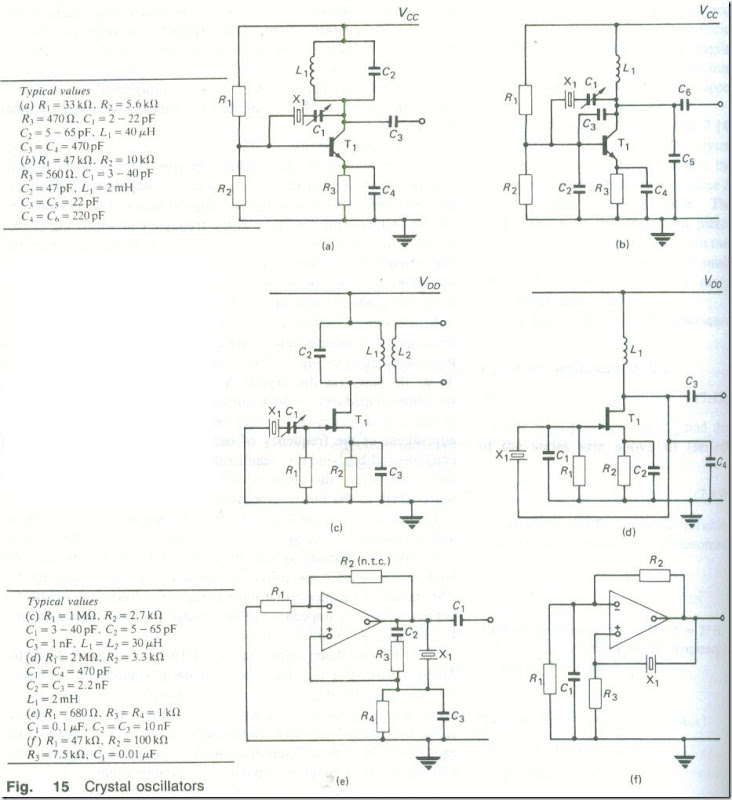
A number of different crystal oscillator circuits have been developed and some examples are given in Fig. 15 . In the bipolar transistor circuit of Fig. 15(a) energy is fed from the collector of T1 to its base via the crystal X1 The crystal should have the minimum impedance at the required oscillation frequency and so it is operated in its series-resonant mode. Capacitor C1 provides fine adjustment of the frequency of oscillation. R1 , R2, R3 and C4 are conventional bias and d.c. stabilization components and the voltage developed across the tuned circuit L1C2 is coupled to the load (or more likely to the buffer amplifier) by capacitor C3.
The circuit shown in Fig. 15(b) is known as the Pierce circuit and is essentially a version of the Colpitts oscillator. The required capacitive impedances joining the collector to the emitter and the base to the emitter are provided, respectively, by C5 and by C2 . The inductive reactance that must connect the base to the collector is provided by the impedance of the crystal in parallel with capacitor C3. Inductor L1 is an r. f. choke.
The FET oscillator shown in Fig. 15(c) is an example of the Miller circuit. For the circuit to oscillate at a particular frequency both the crystal and the drain tuned load must have inductive impedances at that frequency. The necessary feedback from drain to gate is via the internal electrode capacitance of the FET. If the internal capacitance is of insufficient magnitude it can be augmented by the connection of an external capacitor of suitable value.
Another version of the Pierce circuit is given in Fig. 15(d); capacitors C1 and C4 provide the capacitive paths between source and gate and source and drain respectively and the crystal provides the inductive path between drain and gate. Finally, Figs. 15(e) and (f) show the op-amp versions of a crystal oscillator. Circuit (e) is a form of Wien oscillator, while circuit (f) oscillates because positive feedback is applied via the crystal.
When a drain or collector tuned load is employed it is possible to operate a crystal at an overtone frequency (i.e. a multiple of the fundamental frequency). Other circuits cannot do this since a crystal will naturally try to work at its most active frequency where its vibrations are most vigorous. and this is the fundamental. On the other hand, oscillators which do not include a tuned circuit can be provided with the facility to switch different crystals into circuit when rapid frequency changes are desired .
The frequency range of commercially available crystals is from about 10kHz to about 20 MHz with the crystal operating at its fundamental frequency. The higher frequency limit is imposed by the necessary plate thickness becoming extremely small and fragile. When a higher frequency is required two approaches are available, either singly or in combination. Firstly, a crystal can be encouraged to vibrate strongly at an overtone frequency. Secondly, the crystal can be used to generate oscillations at a lower frequency than that wanted and then to increase the oscillation frequency to the desired value by one or more frequency multipliers.
An ordinary crystal oscillator may have a frequency stability of perhaps 1 part in 106. For greater stability the crystal can be mounted in a temperature-controlled environment and may then provide a stability of 1 part in 107 . If very great care is taken even greater frequency stability can be achieved.
Exercises
1- Draw the circuit of a Hartley oscillator and explain its action. Suggest suitable component values if the circuit is to operate at a frequency of 1.5 MHz.
2- A tuned-collector oscillator is tuned to operate at 22 kHz by a variable capacitor set to 2 nF. What is the value of the tuned circuit inductance?
3- An oscillator operates at 2.2 MHz. At what frequency will it work if its tuned circuit capacitance is reduced by 50%?
4- Draw the circuit of a Hartley oscillator using an op-amp, List the function of each component shown. If the circuit has L1 = L2 =30 mH , C1 =0.1 J.l.F, what is the frequency of oscillation? Calculate the gain of the op-amp if R1=39 kΩ and R3=100 kΩ.
5- The frequency of oscillation of a Colpitt’s oscillator is given by 1
where L1, C2 and C3 are the frequency-determining components. Such a circuit operates at 450 kHz with C2 = C3 . What will be the oscillation frequency if the value of C2 is doubled?
6 – The frequency of oscillation of a Hartley oscillator is given by f0 = 1/[2μ√C3(LI+ L2)]
Calculate the oscillation frequency if C3=0.01 μF and LI = L2=25 mh.
7- Draw the circuit of an op-amp Wien oscillator. Calculate its frequency of operation if the frequency-determining resistors are each 10 kΩ and the frequency-determining capacitors are each 0.01 μF.
8- The amplitude of the oscillations in an LC oscillator is often controlled by allowing the output transistor to saturate. Explain why this is not possible for an RC oscillator. Describe the method of amplitude stabilization used.
9- An op-amp can be used as the basis of a Colpitt’s oscillator, a Hartley oscillator and a Wien oscillator. Draw circuits to show the method used in each case.
10- Explain why a change in the ambient temperature may cause a change in the frequency of an LC oscillator.
11- List five factors that may influence the frequency stability of an LC oscillator.
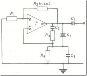
12- Fig. 16 shows the circuit of an op-amp crystal oscillator. Explain the action of the circuit and list the function of each component.
13- For the circuit given if Fig. 16 what would be the effect if (a) R3 were open-circuited, (b) C3 were short-circuited, or (c) R2 were replaced by an ordinary resistor?


