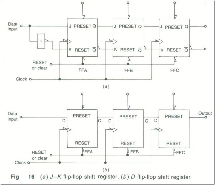
Shift Register
A shift register is a digital circuit which can be used as a temporary store of data. It can be made using either J—K or D flip-flops as shown by Figs .16(a) and (b).
Data to be stored in a register is applied one bit at a time (or serially) to the data input terminal. It is loaded into the register by being shifted one place to the right at the end of each clock pulse. The number of bits of data that can be stored is equal to the number of flip-flops in a register. When the data is wanted it is moved out of the register one bit at a time by further right-shifting. This kind of shift register is of the serial-in, serial-out type (SISO). There are also three other ways in which a shift register may be operated. These are:
(a) Serial-in, parallel-out (SIPO). Now data enters the register one bit at a time as for a SISO circuit but the data is taken from the register as an n-bit word with all bits simultaneously outputted. A SIPO register is often used to convert data from serial format to parallel format.
(b) Parallel-in, parallel out (PIPO). All the bits in the data are entered into the register simultaneously by setting, or clearing, each flip-flop, and they are also outputted simultaneously. Used as a temporary store.
(c) Parallel-in, serial out (PISO). With this kind of shift register data bits are simultaneously entered into the circuit but they are outputted one bit at a time as for a SISO circuit. Used to convert parallel data into serial form.
Both counters and shift registers are available in the TTL and the CMOS logic families. The counters are of either the synchronous or the non-synchronous kinds and may be 4-bit or 8-bit types. Any of them may be either a binary counter or a decade counter. A binary counter is the sort of counter previously described while a decade counter is a 4-bit counter that has had its maximum count reduced to 9 (0 to 9 is 10 different states) by resetting all the internal flip-flops when the count reaches 10; this takes the output of the counter to 0.
An up-down counter is able to count upwards from 0 to some maximum value, say 15, or downwards from 15 to 0. The direction of the count is determined by taking a count-up pin either high or low.
Exercises
1 Draw the circuit of a divide-by-8 counter using (a) synchronous and (b) non-synchronous techniques. Describe the operation of both circuits.
2 Explain, with the aid of truth tables, the difference between an S-R and a J-K flip-flop. Show how the S-R flip-flop can be made using four NAND gates and how clocked operation can be arranged.
3 J-K flip-flops are of either the master-slave or the edge-triggered type. Explain the basic differences between them.
4 Draw the circuit of a shift register that employs three D flip-flops. Briefly explain the action of the circuit when the input data to be stored is 101.
5 What logic level appears at the Q output of a flip-flop when it is (a) SET. (b) CLEARED, (c) RESET. A J-K flip-flop has Q= 1. What is the Q level (i) initially, (ii) after the flip-flop has been toggled?
6 Draw the circuit of an S-R flip-flop using the TTL 7400 NAND gate.
7 The binary signal 1010 is shifted into a 4-bit S1SO shift register. What is the state of each of the four flip-flops after (a) 2 clock periods, (b) 4 clock periods and (c) 6 clock periods?
8 The binary signal 1101 is applied to a S1PO shift register. Draw the input and output waveforms.
9 A division of (a) 100, (b) 64 is required. Suggest how each could be obtained.
10 (a) What is the main difference between a synchronous counter and a non-synchronous counter? (b) What is meant by the terms leading-edge triggered and trailing-edge triggered? Illustrate the answer with waveforms, (c) What is meant by the modulus of a counter? What is the modulus of a 4-bit binary counter?

