Logic Circuits That Meet a Given Specification
1. A machine is to start working only when a start button is pushed by an operator (A), OR a start signal is received from a control point (BJ, AND a protective guard is in place (C) AND the piece to be machined is in position (D). The Boolean equation describing this action is:
F + (A + B)CD
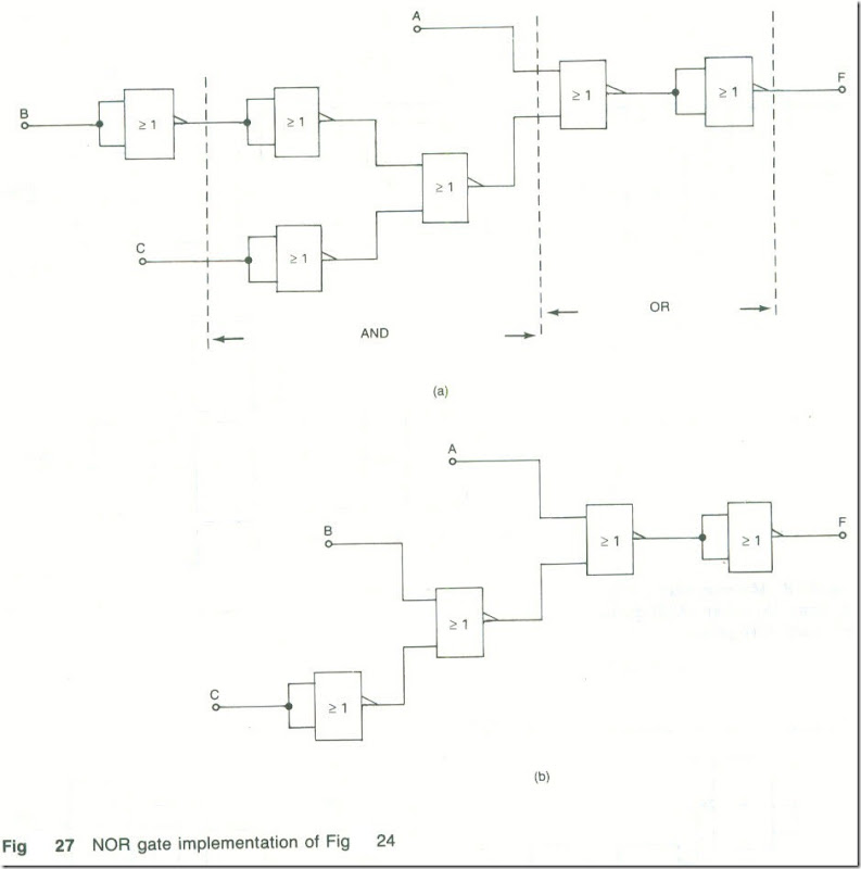
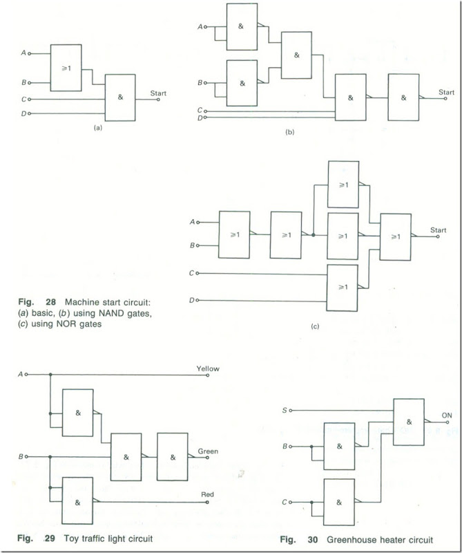
This equation can be implemented using (a) AND and OR gates, (b) NAND gates only or (c) OR gates only.
Fig. 28(a) shows the circuit implemented using one AND gate and one OR gate which requires the use of two ICs.
Referring to Fig. 23 and then replacing the OR gate with its NAND gate alternative, and from Fig. 23 also replacing the AND gate with two NAND gates, gives the circuit shown in Fig. 28(b). The circuit requires the use of five NAND gates and so could be implemented using two ICs.
The NOR gate version of the circuit is shown in Fig. 28(c). The OR gate has been replaced by two cascaded NOR gates and the AND gate has been replaced by three NOR gates.
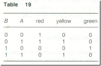
2. A circuit is needed to operate the traffic light used in a toy car display in a shop window. Red, yellow and green LEDs are to be used as the lights which are to follow the UK sequence of red, red and yellow, green, yellow and then red again.
The truth table for the circuits is given by Table 19.
From Table 19
The NAND gate implementation of the circuit is shown in Fig..29.
3. A greenhouse heater is to turn ON automatically when (a) a switch (S) is in the ON position, AND (b) the outside temperature (B) has fallen to below a set value, AND (c) it is dark outside (C).
If B is high when the temperature is above the set value and C is high when it is daytime. then the Boolean equation that describes the operation of the circuit is ![]() . The circuit is shown by Fig 30.
. The circuit is shown by Fig 30.
Exercises
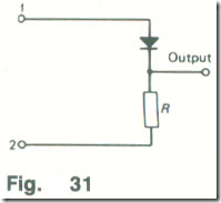
8.1 In the circuit given in Fig. 31 the load resistor R is 1000 Ω. The voltage applied between terminals I and 2 makes terminal 16 V positive with respect 10 terminal 2. When conducting, the diode has a voltage drop of 0.65 V. Calculate the output voltage.
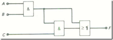
8.2 When A = 8 = 1 and C = 0 find the output F of the circuit shown in Fig. 32.
8.3 The Boolean expression for a circuit is F = ABCDE. Use a truth table to show that the output of the circuit will be at logical 0 whenever C = 0 regardless of the values of the other inputs.
8.4 The Boolean expression for a circuit is F = A + B + C + D + E. Show that the output of the circuit will be at logical I whenever C = 1 regardless of the values of the other inputs.
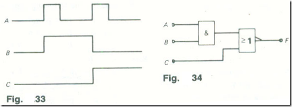
8.5 The waveforms shown in Fig. 33 are applied to the circuit given in Fig. 34. Draw the output waveform F of the circuit.
8.6 Write down the truth table of the circuit given in Fig. 32. Hence obtain the Boolean equation.
8.7 Write down the truth table of the circuit given in Fig. 34. Hence obtain the Boolean equation.
8.8 For the circuit given in Fig. 35 determine the logical value of B if F = I when A = l.
8.9 Write down (a) the truth table and (b) the Boolean expression describing Fig. 8.35.
8.10 The Boolean expression for a logic circuit is F = A.B. CD. Show how the function can be implemented using (a) one gate and (b) two gates.
8.11 The waveforms shown in Fig. 8.33 are applied to Fig. 8.32. Draw the Output waveform.
8.12 Draw circuits to perform the logical functions (a) F = (A + B + C) (D + E). (b) F = A.B.C + D(B + C).
8.13 The voltage table for a logic circuit is given in Table 8.20. What logical function is performed if (a) positive and (b) negative logic is employed?
8.14 The Boolean expression ![]() is to be implemented. Draw the circuit using (a) NAND gates, (b) NOR gates only.
is to be implemented. Draw the circuit using (a) NAND gates, (b) NOR gates only.
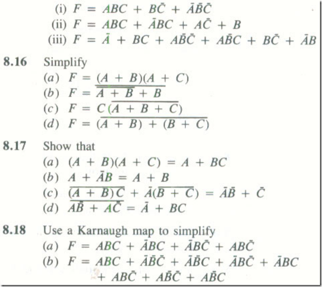
8.15 Simplify the following expressions using a Kamaugh map


