Linear and digital integrated circuits
Most integrated circuits (ICs) are classified as being either linear or digital devices. A linear circuit is one whose output signal has a linear relationship with the input signal. Linear ICs are also known as analogue ICs because the signals that they handle may vary continuously over a range of values. Linear ICs include operational amplifiers (op-amps), audio-frequency power amplifiers and various radio and television circuits. Most linear ICs employ bipolar transistors throughout, although a few types of op-amp have either a JFET or a MOSFET input stage.
Digital ICs operate with binary digital signals that are always in either of two possible states; namely logic 0 and logic 1. Digital ICs include gates, counters, memories and microprocessors. Some ICs include both analogue and digital circuitry; three examples of these ICs are timer, analogue-to-digital converters (ADC) and digital-to-analogue converters (DAC).
Linear Integrated Circuits
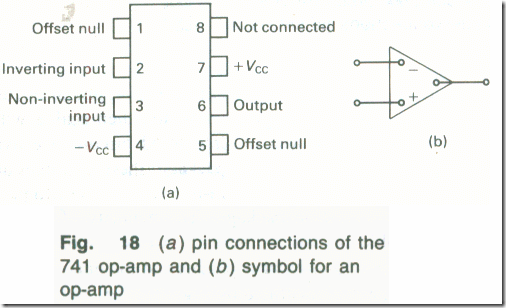
When a linear integrated circuit is used in electronic circuitry a number of external components are also necessary and must be connected to the appropriate terminals of the IC. An operational amplifier, or op-amp, is a high-gain voltage amplifier that has two input terminals and one output terminal. There are a large number of different op-amps on the market made by a variety of manufacturers, but one of the most commonly used is the 741. The pin connections of this op-amp are shown by Fig. 18(a) and the symbol for an op-amp is shown by Fig. 18(b). One of the inputs is labelled as the inverting terminal and the other input is labelled as the non-inverting terminal. A signal applied to the inverting terminal appears at the output terminal inverted, i.e. a sinusoidal input signal will experience 180° phase shift, but a signal applied to the non-inverting terminal will not be inverted. Most op-amps require both positive and negative power supply voltages, although a few types have been designed to work from a single polarity supply.
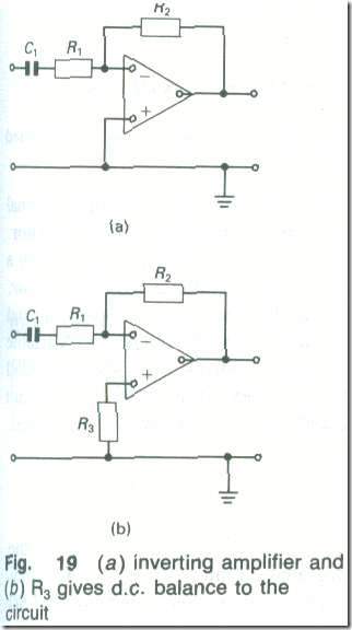
When an op-amp is used as a voltage amplifier it must have two resistors connected between the appropriate terminals to specify the voltage gain. Fig. 19(a) shows the circuit of an inverting amplifier using an op-amp. One resistor R1 is connected between the input terminal of the circuit and the inverting terminal of the op-amp, and the other resistor R2 is connected between the inverting input terminal and the output terminal of the op-amp. The voltage gain Av of the inverting amplifier is
Av = ̶ R2/R1 (5.3)
The input resistance of the amplifier circuit is equal to R1 ohms.
Example 3
An inverting op-amp circuit is to have a voltage gain of 30 and an input resistance of 2000 Ω. Determine values for the resistors R1 and R2.
Solution
The input resistance is to be 2000 Ω and hence R1 = 2000 Ω (Ans.)
From equation (3), R2 = 30 x 2 kΩ= 60 kΩ (Ans.)
The 60 kΩ could be obtained using two 120 kΩ resistors in parallel, or the nearest preferred value of 62 kΩ could be used.
A third resistor, r3, in Fig. 19(b), is often used to d.c. balance the circuit (essential if there is no input coupling capacitor). The value of R3 should be equal to the total resistance of R1 and R2 in parallel,
i,e. R3 = R1/R2/(R1+R2).
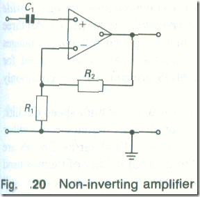
If a non-inverting voltage gain is wanted, the circuit shown in Fig. 20 is used. The voltage gain Av of the circuit is
Av = (R1 + R2)/R1 (5.4)
and the input resistance is very high. If d.c. balance of the circuit is wanted, a resistor R3 is connected in series with the non-inverting terminal.
Example 4
A non-inverting op-amp circuit is to have a voltage gain of 30 and a resistance of 2000 Ω . Determine the component values.
Solution
From equation (4), 30 = (R1 + R2)/R1
2R1 = r2
Choosing a suitable value for R2, say 2 kΩ, R1 = 58 kΩ (Ans.)
The nearest preferred value is 56 kΩ.
To obtain an input resistance of 2 kΩ, a 2 kΩ resistor can be connected across the input terminals of the circuit.
An audio-frequency power amplifier IC will also need some external resistors and it will require at least one external decoupling capacitor.
(A decoupling capacitor is one that is connected in parallel with a resistor to prevent an a.c. voltage being dropped across the resistor. The capacitor has a low reactance at the frequencies of operation and effectively short-circuits the resistor at those frequencies.) Variable resistors, such as volume and tone controls, are also provided externally. Any inductors that may be needed in an analogue circuit cannot be provided within an IC and will also be externally connected.


