Frequency Characteristics
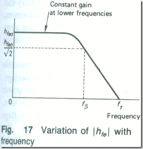
The current gain of a transistor is not the same value at all frequencies, but, instead, falls off at the higher frequencies (see Fig. 17). The frequency at which the magnitude of the current gain hfe has fallen to 1/√2 times its low-frequency value hfeo is known as the cut-off frequency fβ of the transistor. Eventually, at some frequency ft, falls to unity. The high-frequency performance of a transistor is often quoted by the manufacturer in terms of a parameter ft where
ft = │hfe │.f (3.20)
f being any frequency .
ft is known as the transition frequency or as the common-emitter gain-bandwidth product.
Example 8
A transistor has ft = 500 MHz. What is its current gain at (a) 100 MHz (b) 10 MHz?
Solution
(a) ft = 500 MHz = │hfe│ X 100 MHz
│hfe│ = 5 (Ans.)
(b) ft = 500 MHz = │hfe│ X 10 MHz
│hfe│= 50 (Ans.)
Fig.18 shows how the transition frequency of a typical transistor varies with the collector current. Clearly, if the device is to operate at a high frequency, the collector current must be carefully chosen.
Thermal Runaway
An increase in the temperature of the collector-base junction will cause the collector leakage current Icbo to increase. The increase in collector current produces an increase in the power dissipated at the collector-base junction and this, in turn, further increases the temperature of the junction and so gives a further increase in ICBO. The process is cumulative and, particularly in the common-emitter connection of a germanium transistor, could lead to the eventual destruction of the transistor. In practice, thermal runaway is prevented in well-designed circuits by the use of d.c. stabilization circuitry that compensates for any increase in ICBO and also, for power transistors, by the use of a heat sink to provide rapid conduction of heat away from the junction. Thermal runaway is rarely a problem with silicon transistors because their leakage current is so small.
The manufacturer of a transistor quotes the maximum permissible power that can be dissipated within the transistor without damage. The power dissipated within a transistor is predominantly the power which is dissipated at its collector-base junction, and this, in turn, is equal to the d.c. power taken from the collector supply voltage minus the total output power (d.c. power plus a.c. power). For transistors handling small signals, the power dissipated at the collector is small and generally there is Hide problem. When the power dissipated by the transistor is large enough to cause die junction temperature to rise to a dangerous level, it is necessary to improve the rate at which heat is removed from the device. Power transistors are constructed with their collector terminal connected to their metallic case. To increase the area from which the heat is removed the case of the transistor can be bolted on to a sheet of metal known as a heat sink. Heat will move from the transistor to the heat sink by conduction and is then removed from the sink by convection and radiation.
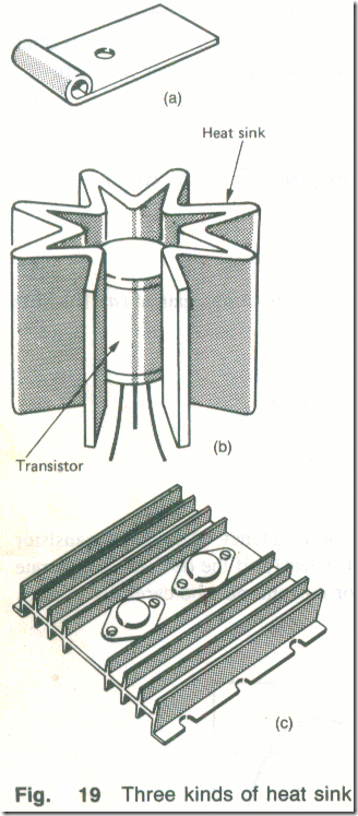
The simplest heat sink is shown in Fig. 19(a). It consists of a push-fit clip that can be screwed on to a metal chassis, the transistor being a push-fit into the hole. The greater the power dissipated within a transistor, the larger the surface area of the heat sink required to remove sufficient heat to keep the junction temperature within safe limits. To prevent the heat sink occupying too much space within an equipment, it is common to employ structures of the kinds shown in Figs. 19(b) and .19(c).
For maximum efficiency a heat sink should (i) be in excellent thermal contact with the transistor case, (ii) have the largest possible surface area and be painted matt black and (iii) be mounted in a position such that a free flow of air past it is possible.


