When a fluid completely fills a vessel, and pressure is applied to it at any part of the surface, that pressure is transmitted equally throughout the whole of the enclosed fluid. This is known as Pascal’s principle.
The transmission of pressure in fluids. Pascal’s principle
This fact, first recognized by the French scientist and philosopher, Pascal, in 1650, is called the principle of transmission of pressure in fluids.
Illustration of Pascal’s principle: 
The image above shows a piece of apparatus to demonstrate this principle.
It consists of a glass barrel fitted with a plunger and ending in a bulb pierced with holes of uniform sizes. It is filled with water by dipping the bulb in water and slowly raising the plunger.
When the plunger is pushed in the water squirts equally from all the holes. This shows that the pressure applied to the plunger has been transmitted uniformly throughout the water.
Important industrial application
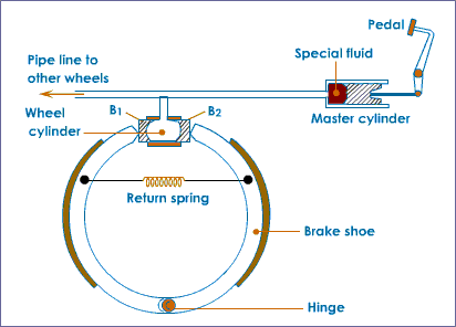
The principle of transmission of pressure has a number of practical application. Indeed, our lives may often be said to depend on it whenever we ride in a motor vehicle, since the brakes of the majority of road vehicles are worked by hydraulic pressure. The system of braking is shown diagrammatically in the image below.

The brake-shoes are expanded by a cylinder having two opposed pistons. These are forced outwards by liquid under pressure conveyed by a pipe from the master cylinder. The piston of the master cylinder is worked by the brake pedal.
When pressure on the pedal is released the brake-shoe pull-off springs force the wheel pistons back into the cylinders, and the liquid is returned to the master cylinder.
A very important advantage of this system is that the pressure set up in the master cylinder is transmitted equally to all four wheel cylinders so that the braking effort is equal on all wheels.
The hydraulic press
This type of machines has numerous uses, from the compression of soft materials such as waste paper and cotton into compact bales to the shaping of motor-car bodies and the forging of steel armor plate and light alloys.

In its simplest form the hydraulic press consists of a cylinder and piston of large diameter, connected by a pipe to a force pump of much smaller diameter.
Oil from a supply tank is pumped into the cylinder and the piston ( or ram) moves out, exerting considerable force.
A valve is provided to release the pressure and allow the oil to return to the tank, after the press has done its work.
In order to understand how very large forces may be so easily produced by this press, look at the image below and continue reading to the equation of Pascal’s principle :).

To derive Pascal’s equation
Suppose the pump barrel has an area of 2 cm² and that a force of 10 Newton is applied to its plunger,
the pressure produced = force / area = 10/2 = 5 N/cm².
This pressure is transmitted equally throughout the whole of the liquid and so also to the piston in the large cylinder.
Now, if the area of the large piston is 800 cm², then the total force or thrust exerted is given by,
thrust = pressure × area = 5 × 800 = 4000 N.
A force of 4000 N is therefore obtained simply by exerting a force of only 10 N.
The velocity ratio between the two cylinders
The velocity ratio may be found by using the fact that the volume of liquid which leaves the pump cylinder is equal to that which enters the ram cylinder.
If x is the distance moved by the pump piston and y the distance moved by the ram piston, then equating volumes,
x × area of pump piston = y × area of ram piston
or
velocity ratio = x / y = area of ram piston / area of pump piston
= Π R² / Π r² = R² /r²
where R = radius of ram piston, and
r = radius of pump piston.
The above expression gives the velocity ratio between the two pistons only. If the total velocity ratio of the whole press is required we must multiply R²/r² by the velocity ratio of the pump handle treated as a lever.
